Optical disk apparatus and optical disk identifying method

a technology of optical disks and optical discs, applied in the field of optical disc drives, can solve the problems of disc discrimination errors, time cannot be measured precisely, time cannot be precisely measured, etc., and achieve the effect of more precisely discriminating a kind of discs

Inactive Publication Date: 2005-07-14
PANASONIC CORP
View PDF1 Cites 12 Cited by
  • Summary
  • Abstract
  • Description
  • Claims
  • Application Information

AI Technical Summary

Benefits of technology

[0030] With this aspect, since the optical disc drive uses a pickup in which a focus deviation is generated between leaser beam which passes through an outer periphery of the objective lens and leaser beam which passes through an inner periphery of the objective lens by a difference in base material thickness of optical disc, the amplitudes of the maximum value FEmax and the minimum value FEmin can be made different from each other, and it is possible to discriminate a kind of the disc more precisely.

Problems solved by technology

For this reason, this conventional technique has a problem that the time can not be measured precisely and discrimination error of discs is generated.
Further, there are problems that the sum signal 61 of the base material surface has a small amplitude, noise is erroneously detected as the sum signal 61 of the base material surface, time can not be measured precisely and discrimination error of discs is generated.

Method used


Image

  • Optical disk apparatus and optical disk identifying method
  • Optical disk apparatus and optical disk identifying method
  • Optical disk apparatus and optical disk identifying method

Examples


Embodiment Construction

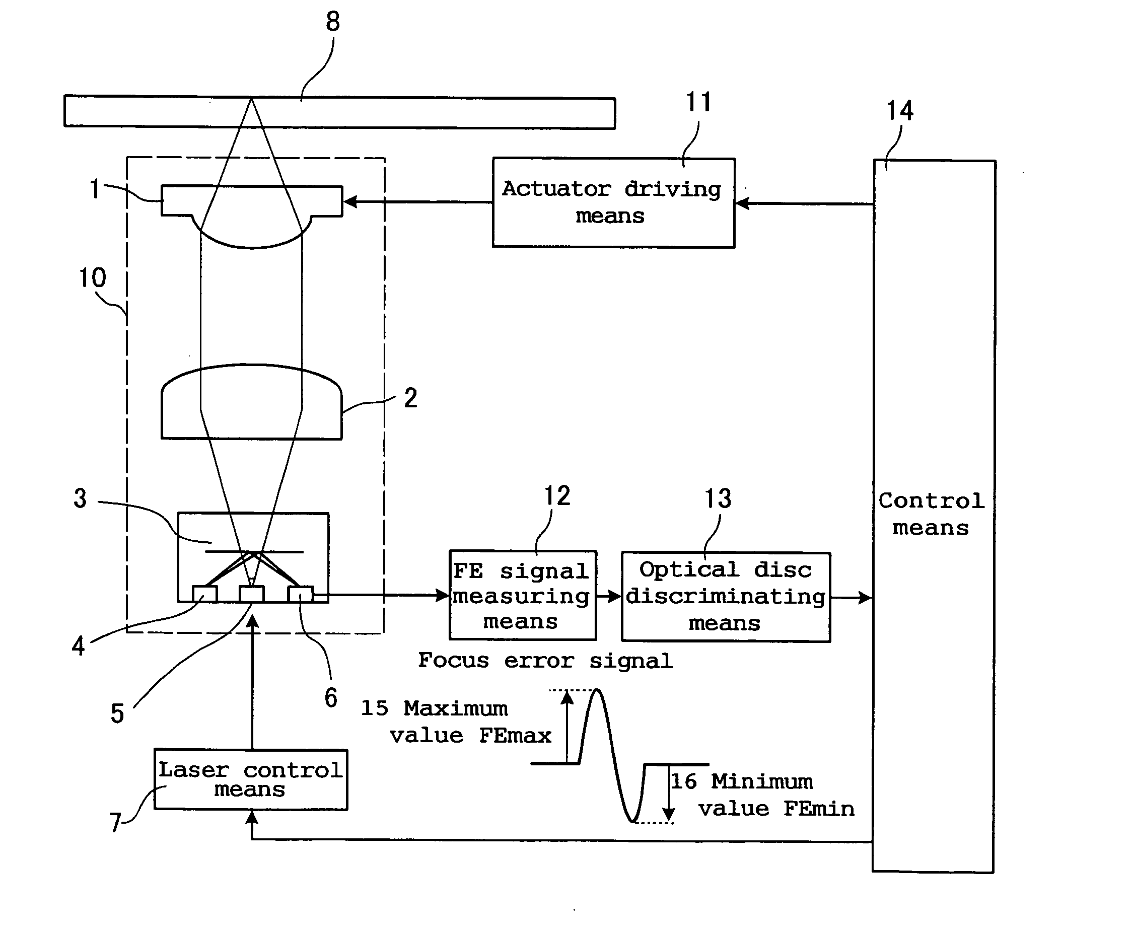
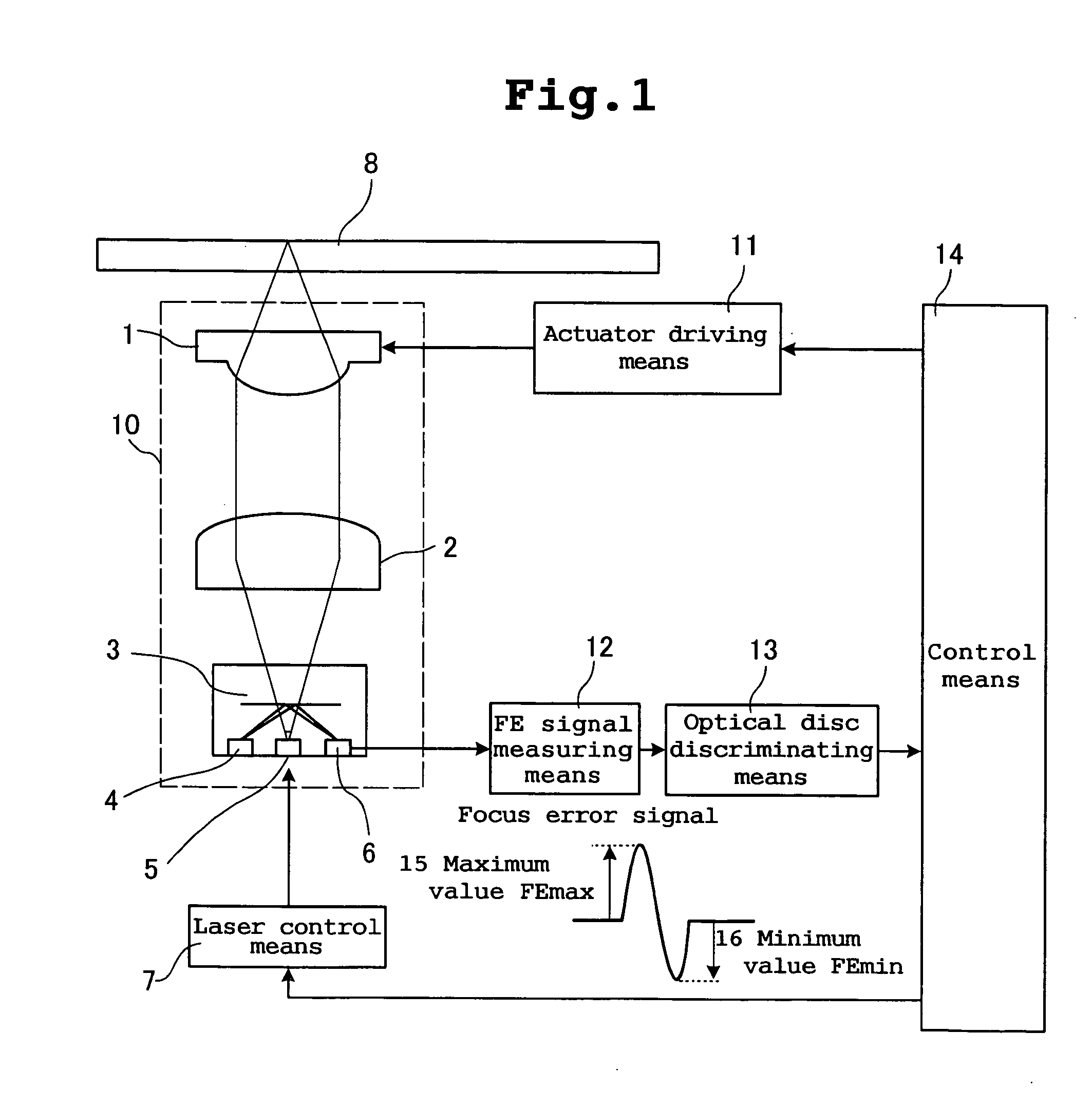
[0039] An optical disc drive according to an embodiment of the present invention will be explained using FIGS. 1 to 3.

[0040]FIG. 1 is a block diagram of the optical disc drive according to the embodiment. A pickup 10 can obtain a playback signal from different kinds of optical discs such as CDs and DVDs and write a recording signal into different kinds of optical discs such as CDs and DVDs. The pickup 10 includes a semiconductor laser 5, a condensing lens 2, an objective lens 1, a polarizing hologram 3, a tracking detection photoreceiving means 4 and a focus detection photoreceiving means 6. The semiconductor laser 5 emits laser having appropriate power under control of laser control means 7. In order to resolve a focus error and a tracking error, the objective lens 1 can respectively move in a focus direction and a diameter direction of the disc in response to a driving signal from an actuator driving means 11.

[0041] The condensing lens 2 converts laser beam irradiated from the s...


PUM

PropertyMeasurementUnit
thicknessaaaaaaaaaa
thicknessaaaaaaaaaa
thicknessaaaaaaaaaa

Abstract

In an optical disc drive capable of recording and playing back different kinds of optical discs, an actuator driving means brings an objective lens close to the optical disc, focus error signals are generated in front of and behind a position where leaser beam comes into focus on a signal surface of the optical disc, optical disc discriminating means discriminates a thickness of the optical disc from a difference in waveform of the focus error signal which is generated by focus deviation between leaser beam which passes through an outer periphery of the objective lens and leaser beam which passes through an inner periphery of the objective lens, and discriminates a kind of the optical disc from the thickness of the optical disc.

Description

TECHNICAL FIELD [0001] The present invention relates to an optical disc drive capable of recording and playing back different kinds of optical discs, and a discriminating method of optical disc for discriminating kinds of optical discs. BACKGROUND TECHNIQUE [0002] There is a conventionally known discriminating method of kinds of optical discs based a difference in base material thicknesses of optical discs. [0003]FIG. 7 shows such a conventional discriminating method of optical discs. [0004] First, a discriminating method of optical discs disclosed in Japanese Patent Application Laid-open No. H8-287588 will be explained. [0005] In this conventional technique, if an objective lens 1 shown in FIG. 7 is brought close to a CD 52 or a DVD 53, a sum signal 55 having a small amplitude based on light reflected from the disc is obtained at a position where laser beam comes into focus on a base material surface 54. Then, if the objective lens 1 is brought further close to the CD 52 or the DVD...

Claims


Application Information

Patent Timeline
Patent Type & Authority Applications(United States)
IPC IPC(8): G11B7/00G11B7/085G11B19/12
CPCG11B2007/0006G11B19/12
Inventor HORIMOTO, NOBUO
Owner PANASONIC CORP
Why Eureka
Try Eureka