Exposure apparatus and device manufacturing method

a technology of equipment and manufacturing method, applied in the direction of photomechanical equipment, instruments, printers, etc., can solve the problem of delay in the start of the exposure, and achieve the effect of increasing the productivity upon movement and shortening the tim

Inactive Publication Date: 2005-10-06
CANON KK
View PDF15 Cites 14 Cited by
  • Summary
  • Abstract
  • Description
  • Claims
  • Application Information

AI Technical Summary

Benefits of technology

[0007] The present invention has been made to overcome the conventional drawbacks, and has as its illustrative object to shorten the time until exposure or a process starts, and increase the productivity upon movement between below a substrate processing system and below an exposure optical system.
[0009] The present invention can shorten the time until exposure or a process starts, and increase the productivity upon movement between below the substrate processing system and below the exposure optical system.

Problems solved by technology

As a method of setting the reference position, the substrate stage is abutted against the reference position in the Z direction, or the reference portion is detected by a detection optical system, but these methods delay the start of exposure.
This poses a problem particularly when a displacement sensor such as an interferometer is used as the position measurement means.

Method used


Image

  • Exposure apparatus and device manufacturing method
  • Exposure apparatus and device manufacturing method
  • Exposure apparatus and device manufacturing method

Examples


first embodiment

[0050] An exposure apparatus as a preferred embodiment of the present invention will be illustratively explained.

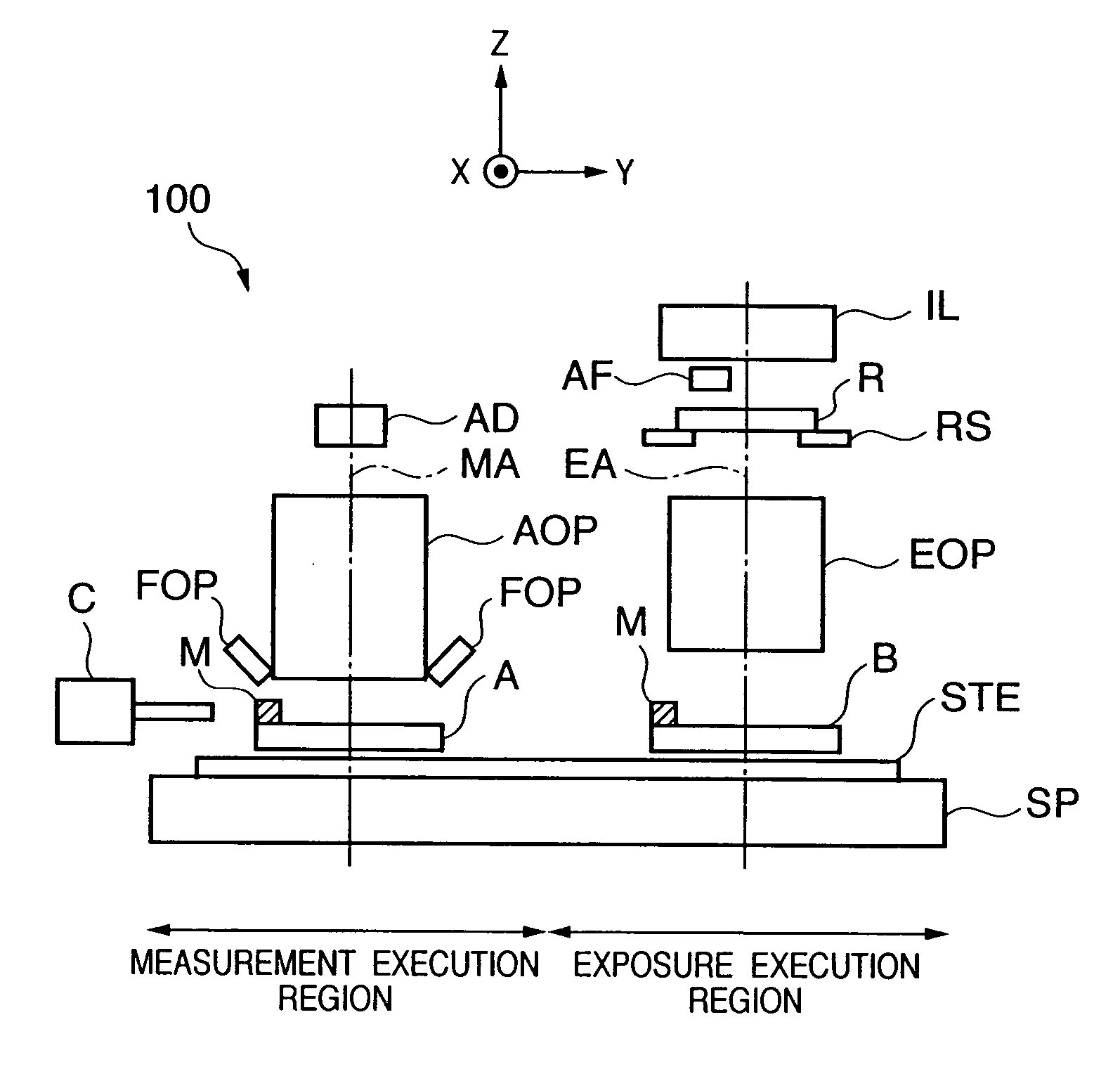
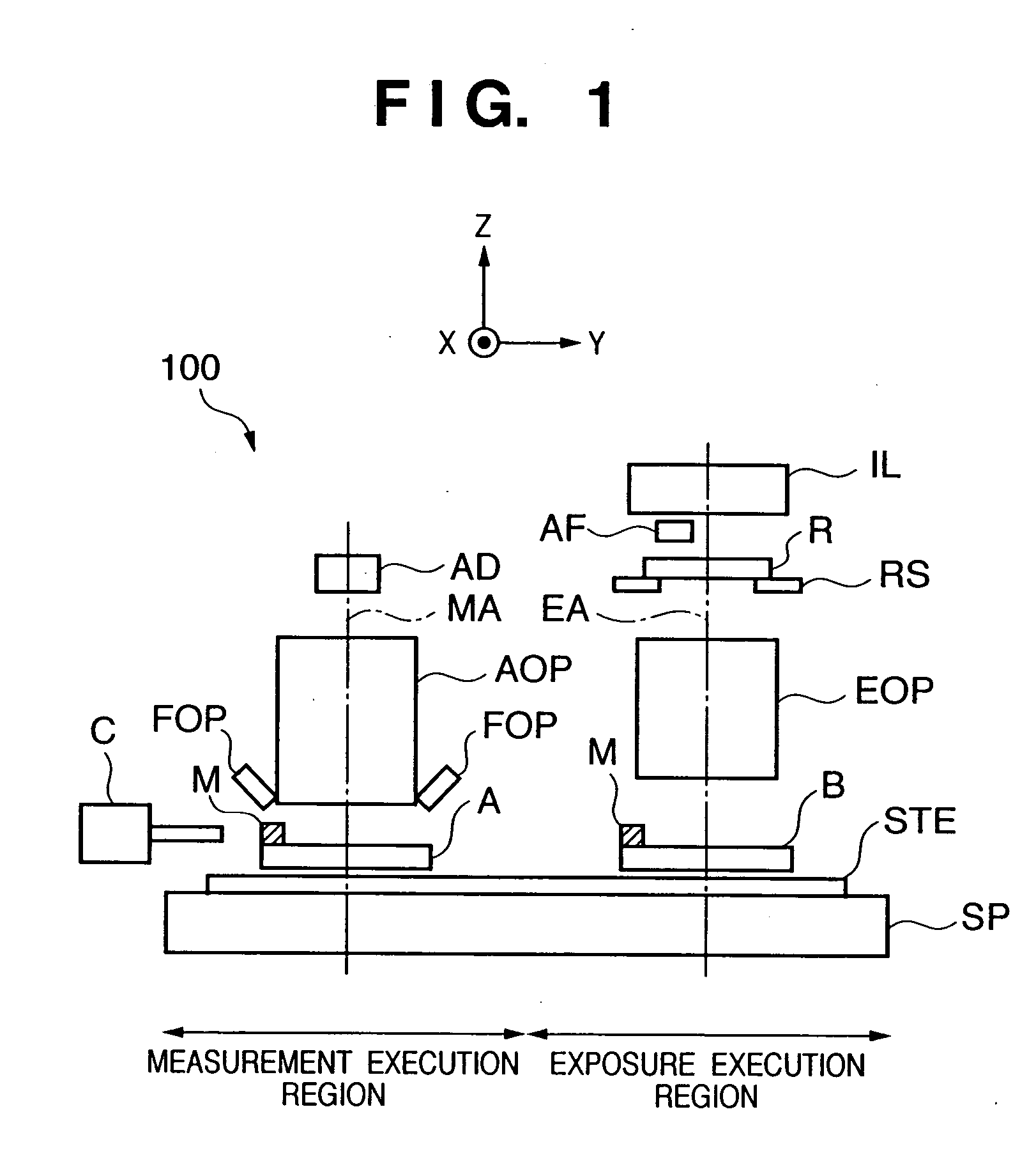
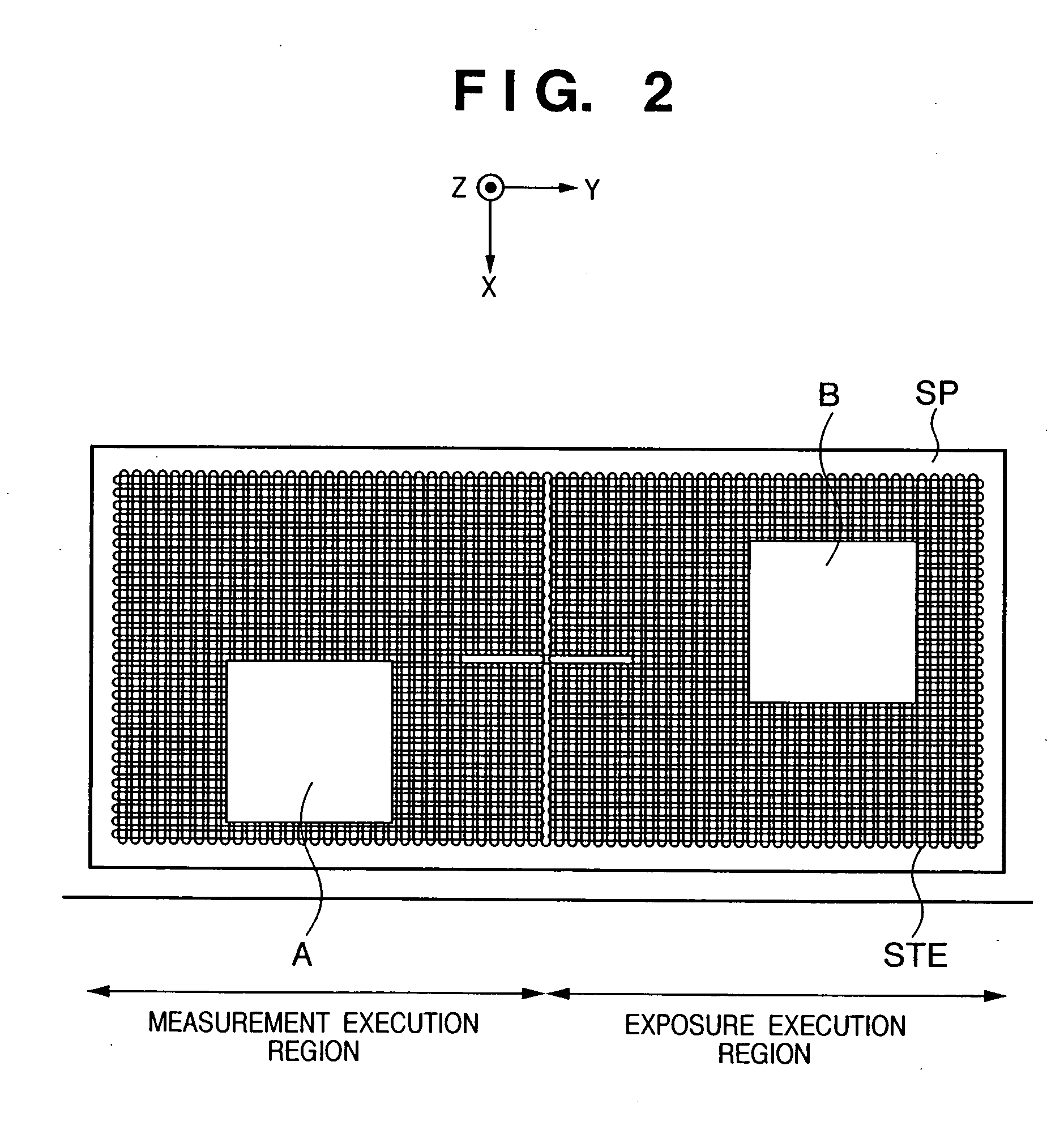
[0051]FIG. 1 is a front view schematically showing the arrangement of the exposure apparatus according to the preferred embodiment of the present invention. FIG. 2 is a plan view schematically showing the arrangement of a stage device mounted on the exposure apparatus shown in FIG. 1. An exposure apparatus 100 shown in FIGS. 1 and 2 is constituted as an apparatus for manufacturing a device such as a semiconductor device.

[0052] The exposure apparatus 100 comprises a stage device having two stages which respectively operate, drive, or position two substrates. The stage device is constituted including a stage surface plate, two stages, driving units (actuators) for driving the two stages, and the like. In the embodiment shown in FIGS. 1 and 2, a stator STE formed from a coil array is arranged on a stage surface plate SP, and two stages A and B are arranged on the stator ST...

modification to first embodiment

[0095]FIGS. 13 and 14 are views showing modifications to measurement in the Y direction, ωx, and ωy. In these modifications, similar to the above-described embodiment, both the stages A and B have X positions at which they are irradiated with Y measurement interferometer beams from two directions.

[0096] In the arrangement example shown in FIGS. 3A to 3C, the interferometer beam groups LY1 and RY2 are arranged along substantially the same axis, and the interferometer beam groups LY2 and RY1 offset from this axis in opposite directions. In a modification shown in FIG. 13, an offset is set in the X direction between the interferometer beam groups LY1 and RY2. Also in this modification, both the stages A and B have X positions at which they are irradiated with Y measurement interferometer beams from two directions. In another modification shown in FIG. 14, the X positions of the interferometer beam groups LY1 and RY1 are the same, and the X positions of the interferometer beam groups L...

second embodiment

[0099]FIGS. 17A to 17C are views schematically showing the arrangement of a measurement system according to the second embodiment of the present invention. FIG. 17A is a plan view, FIG. 17B is a front view, and FIG. 17C is a side view. The second embodiment of the present invention is the same as the first embodiment except the Z measurement method.

[0100] In the first embodiment, the Z measurement mirrors of the stages A and B are the mirrors M5 and M6 which form 45° with respect to the horizontal plane, and Z measurement mirrors fixed to the measurement surface plate are the mirrors ZMU1, ZMU3, ZMD1, and ZMD3 parallel to the X-Y plane. In the second embodiment, the Z measurement mirrors of stages A and B are plane mirrors M7 and M8 parallel to the X-Y plane, and Z measurement mirrors fixed to the measurement surface plate are triangular mirrors ZMU11, ZMU12, ZMD11, and ZMD12 which form 45° with respect to the horizontal plane. Relay mirrors Z1 and Z2 are also triangular mirrors ha...


PUM

PropertyMeasurementUnit
angleaaaaaaaaaa
lengthaaaaaaaaaa
opticalaaaaaaaaaa

Abstract

The start of exposure or a process delays because reference alignment such as abutment must be executed along the optical axis after a substrate stage is moved between the exposure position and the processing position. To solve this problem, an exposure apparatus according to this invention includes an exposure optical system which exposes a substrate to a pattern, a substrate processing system which performs a predetermined process for the substrate at a position apart from the exposure optical system, a substrate stage which moves along a plane perpendicular to the optical axis of the exposure optical system, and a measurement device which continuously measures the position of the substrate stage along the optical axis in the moving range of the substrate stage while the substrate stage moves from below the substrate processing system to below the exposure optical system.

Description

FIELD OF THE INVENTION [0001] The present invention relates to an exposure apparatus and a device manufacturing method using the exposure apparatus. BACKGROUND OF THE INVENTION [0002] Exposure apparatuses which manufacture devices such as a semiconductor device have tackled an increase in productivity. In order to increase the productivity, there has recently been developed an exposure apparatus in which a plurality of substrate stages for supporting a substrate are arranged and exposure and other processes are simultaneously performed. [0003] An example of processes other than exposure is a measurement process for focusing or alignment (positioning). In this case, a measurement optical system for focusing or alignment is arranged at a position apart from an exposure optical system. [0004] Japanese Patent Laid-Open No. 2002-280283 discloses a technique of increasing the productivity by arranging two substrate stages for supporting a substrate and executing exposure and alignment inf...

Claims


Application Information

Patent Timeline
Patent Type & Authority Applications(United States)
IPC IPC(8): G03F9/00G03F7/20H01L21/027H01L21/68
CPCG03F7/70641G03F7/70775G03F7/70733H01L21/67259
Inventor KORENAGA, NOBUSHIGENISHIMURA, NAOSUKE
Owner CANON KK
Why Eureka
Try Eureka