Dither matrix producing method and apparatus, image processing method and apparatus, image forming method and apparatus, program and recording medium

a matrix and matrix technology, applied in the field of dither matrix producing method and apparatus, image processing method and apparatus, image forming method and apparatus, program and recording medium, etc., can solve the problems of insufficient tone reproducibility, adverse influence due to the spread of each dot, and degraded tone characteristics

Inactive Publication Date: 2005-10-06
RICOH KK
View PDF8 Cites 27 Cited by
  • Summary
  • Abstract
  • Description
  • Claims
  • Application Information

AI Technical Summary

Problems solved by technology

Due to the dot gain, an image having a darker tone than an intended one may be output, and thus, tone characteristics may degrade.
That is, in a unit in which dots are overlapped, spreading of each dot cancels out each other, and thus, adverse influence due to the spreading of each dot does not actually appear.
Thereby, this type of dither matrix has a function of maintaining a resolution at a high level, while having a demerit that tone reproducibility may not be sufficient.
Thus, this type dither matrix may not be up-to-date one recently.
In the basic matrix shape producing method disclosed by Japanese Laid-open Patent Application No. 2003-163806, although the requirement that basic matrix shape is cyclically disposed is fulfilled, the following problem may occur.
Since the basic matrix central position thus may vary, there may occur a problematic situation in which, if a common growth rule is applied to determine a pixel growth order in the basic matrix, a growth order in a halftone dot may not agree with each other.
Furthermore, according to the method of Japanese Laid-open Patent Application No. 2003-163806, it is not possible to determine a growth order only based on a pixel arrangement in the basic matrix.
In such a case, it is not possible to determine the growth order only from information concerning a distance from the growth center of the relevant basic matrix.
Furthermore, the method of Japanese Laid-open Patent Applica...

Method used


Image

  • Dither matrix producing method and apparatus, image processing method and apparatus, image forming method and apparatus, program and recording medium
  • Dither matrix producing method and apparatus, image processing method and apparatus, image forming method and apparatus, program and recording medium
  • Dither matrix producing method and apparatus, image processing method and apparatus, image forming method and apparatus, program and recording medium

Examples


first embodiment

[0044] In particular, a process of determining a basic matrix shape in a process of producing the dot concentration type dither matrix is generally difficult since there is a requirement that the basic matrix should be disposed cyclically. Therefore, an ideal basic matrix shape cannot be derived easily according to the prior art. As a result, there may frequently occur a problematic situation in which the basic matrix shape, which has not compatible with a dot growth order in the dot concentration type dither matrix, is produced. Consequently, it should be efficient to produce the dither matrix trusting experience or intuition of an expert in the prior art. For example, as described later, the present invention has a basic matrix shape as shown in FIG. 4, for example. By disposing it in such a manner as to achieve a cyclic structure designated by a main vector and a sub-vector, it becomes possible to achieve an ‘exactly fit’ arrangement as shown in FIG. 7. At this time, a fact that ...

second embodiment

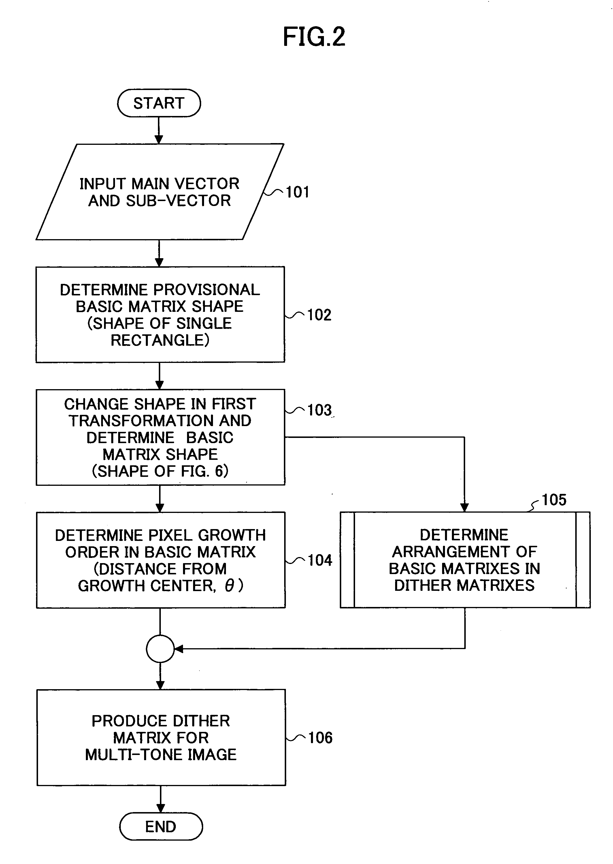
[0057] According to the present invention, a dither matrix producing method to arrange basic matrixes cyclically includes the steps of: a) defining two vectors determining a cyclic structure of the basic matrixes as below:

main vector: m{circumflex over ( )}=(mx, my); and

sub-vector: s{circumflex over ( )}=(sx, sy);

[0058] b) defining a positional vector of a pixel of the basic matrix, as below:

Pi{circumflex over ( )}=(Pix, Piy)

where the suffix i denotes an i-th pixel of the basic matrix; c) arranging the pixels of the basic matrix in such a manner to fulfill a requirement of the cyclic structure determined in the step a); then, d) performing transformation according to the following formula:

Pi{circumflex over ( )}→Pi{circumflex over ( )}+km{circumflex over ( )}+ls{circumflex over ( )}

where k and l are arbitrary integers which may be negative values, and thus, applying Pi{circumflex over ( )}+km{circumflex over ( )}+ls{circumflex over ( )} as a new pixel positional vector Pi{circumfl...

third embodiment

[0060] According to the present invention, a dither matrix producing method in which a cyclic structure of basic matrixes is determined by two vectors, includes the steps of a) defining the two vectors as below:

main vector: m{circumflex over ( )}=(mx, my); and

sub-vector: s{circumflex over ( )}=(sx, sy);

[0061] b) defining a positional vector of a pixel of the basic matrix, as below:

Pi{circumflex over ( )}=(Pix, Piy)

where the suffix i denotes an i-th pixel of the basic matrix; c) arranging the pixels of the basic matrix in such a manner that arrangement of the pixels of the basic matrix fulfils a requirement of the following formula:

|Pi{circumflex over ( )}|≦|Pi{circumflex over ( )}+km{circumflex over ( )}+ls{circumflex over ( )}|

where k and l are arbitrary integers, which may be negative values or zeros.

[0062] As a result of producing the basic matrix shape according to the above-mentioned relationship according to the third embodiment of the present invention, it is possible to s...


PUM


Abstract

A main vector: m{circumflex over ( )}=(mx, my) and a sub-vector: s{circumflex over ( )}=(sx, sy) determining cyclic structure of a basic matrix are defined, and a positional vector for a pixel configuring the basic matrix Pi{circumflex over ( )}=(Pix, Piy) is defined, where the suffix i denotes an i-th pixel configuring the basic matrix. Then, the pixels configuring the basic matrix are arranged in such a manner as to satisfy the cyclic structure, and transformation of Pi{circumflex over ( )}→Pi{circumflex over ( )}+km{circumflex over ( )}+ls{circumflex over ( )} is carried out where k and l are arbitrary integers, and may be negative values. Then a new shape of the basic matrix is obtained with Pi{circumflex over ( )}+km{circumflex over ( )}+ls{circumflex over ( )} as a new pixel positional vector Pi{circumflex over ( )}.

Description

[0001] The present application claims priority to the corresponding Japanese Application No. 2003-402751 filed on Dec. 2, 2003 and Japanese Application No. 2004-314013 filed on Oct. 28, 2004, the entire contents of which are hereby incorporated by reference. BACKGROUND OF THE INVENTION [0002] 1. Field of the Invention [0003] The present invention relates to a method and an apparatus for producing a dither matrix (threshold matrix) required for performing quantization processing on an multi-tone image, image processing method and apparatus, image forming method and apparatus, a program and a computer readable information recording medium. The present invention is advantageous when it is used in an image forming apparatus using an electrophotographic system such as a laser printer. [0004] 2. Description of the Related Art [0005] Image data input to an image forming apparatus such as a copier, a printer or such has multi-tone data of 8 through 12 bits for each pixel in a case where the...

Claims


Application Information

Patent Timeline
IPC IPC(8): B41J2/52G06T5/00H04N1/405H04N1/52
CPCH04N1/4058
Inventor YASUTOMI, KEIOGAWA, TAKESHITAKESUE, TOSHIHIRO
Owner RICOH KK
Why Eureka
Try Eureka