

Charge storage device
a storage device and charge technology, applied in secondary cell servicing/maintenance, cell components, electrochemical generators, etc., can solve the problems of increasing resistance, reducing the maximum achievable operating voltage, and degrading the capacitor performan
- Summary
- Abstract
- Description
- Claims
- Application Information
AI Technical Summary
Benefits of technology
Problems solved by technology
Method used
Image

Examples
Embodiment Construction
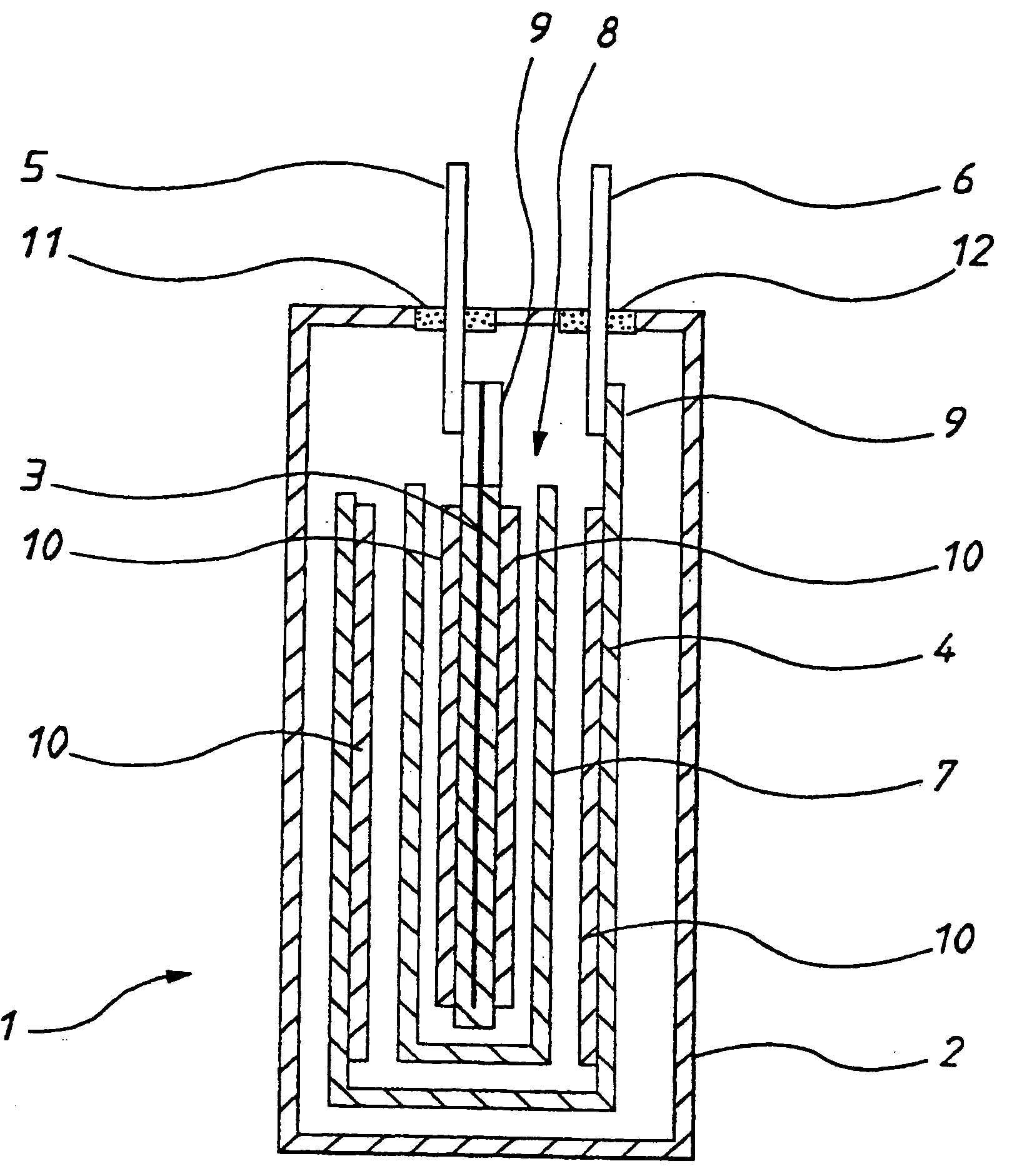
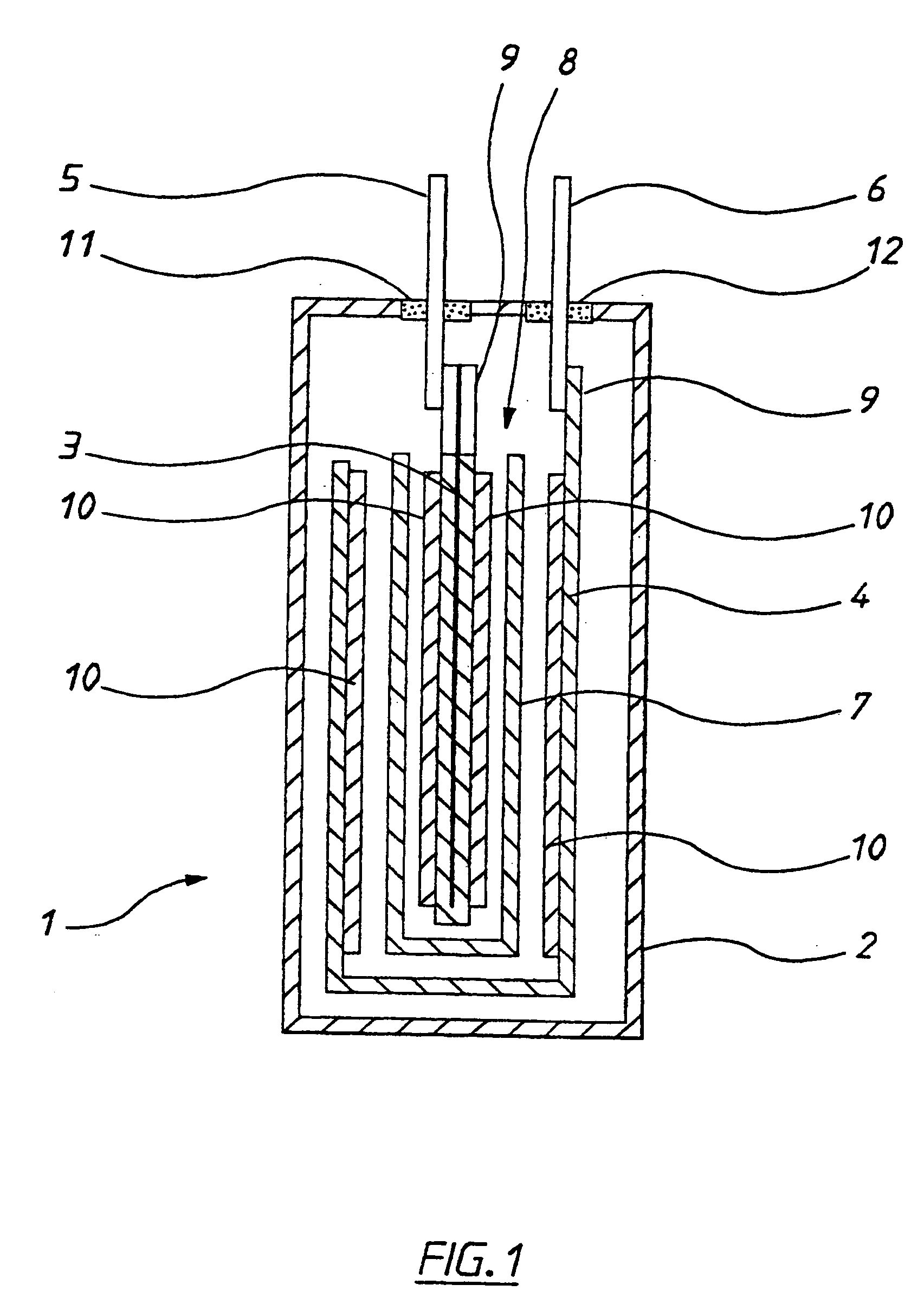
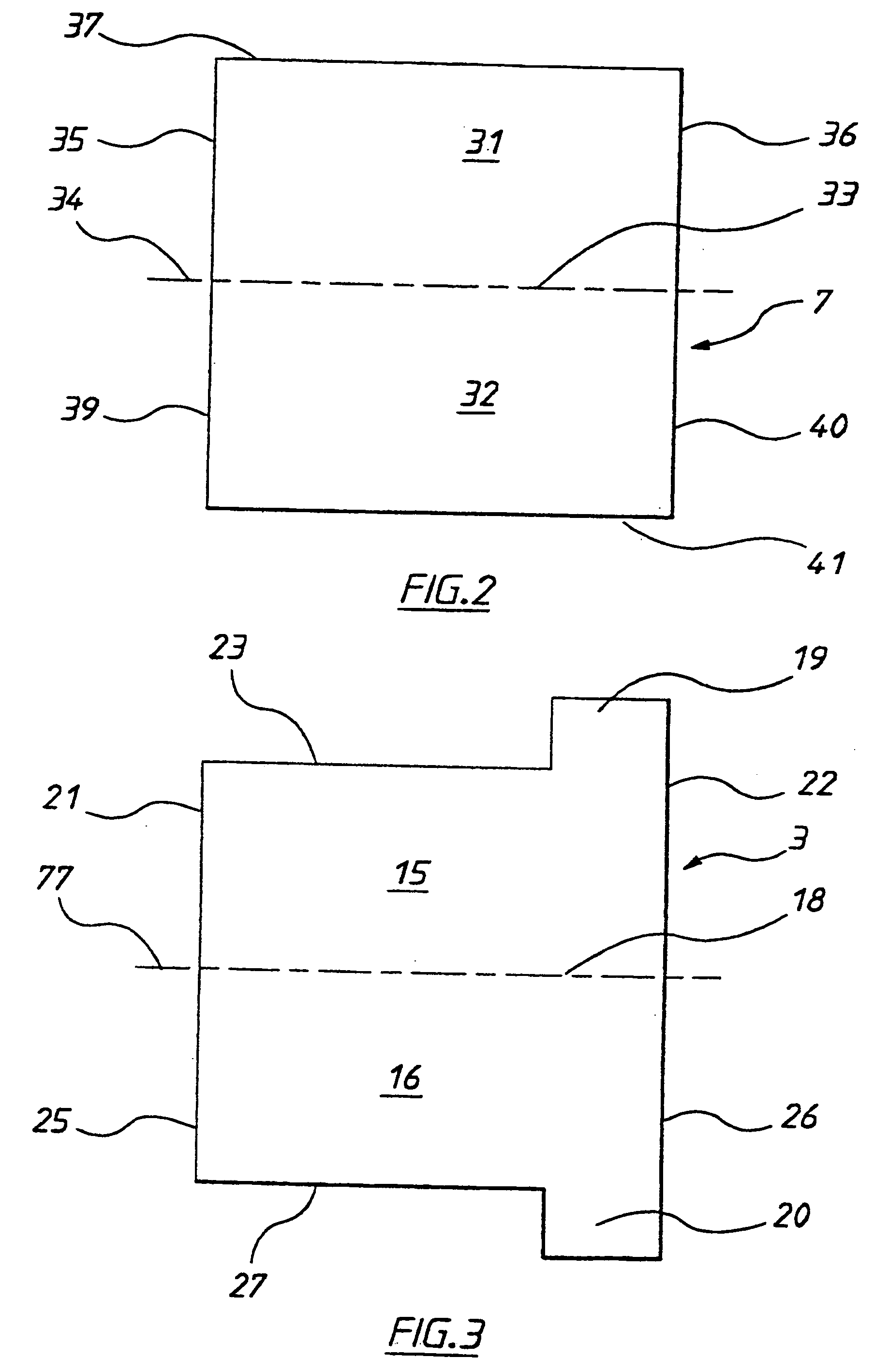
[0075] Referring to FIG. 1, a charge storage device 1 includes a sealed prismatic housing 2. Two opposed folded rectangular aluminium electrodes 3 and 4 are disposed within housing 2 and connected to respective metal terminals 5 and 6 for allowing external electrical connection to the electrodes. A Solupor™ sheet separator 7 is disposed intermediate electrodes 3 and 4 for maintaining those electrodes in a fixed spaced apart configuration. An electrolyte (not shown) is also disposed intermediate the electrodes. Collecting means in the form of a scavenging agent is grafted to separator 7 for sequestering one or more predetermined contaminants from the housing.
[0076] Separator 7 is formed in a “pocket” configuration, when it is folded back upon itself and the transverse ends secured together for providing an opening 8 between the transverse ends. For ease of illustration, separator 7 is shown as having two fold lines. In practice, however, a single fold line is used as the separator i...
PUM
| Property | Measurement | Unit |
|---|---|---|
| capacitance | aaaaa | aaaaa |
| area | aaaaa | aaaaa |
| electric | aaaaa | aaaaa |
Abstract
Description
Claims
Application Information