Electronic device

a technology of electronic devices and power supply, applied in the field of electronic devices, can solve the problems of large power consumption, difficult to reduce power consumption, and increase power consumption, and achieve the effect of reducing power consumption and suppressing power consumption

Inactive Publication Date: 2005-10-06
YOKOGAWA ELECTRIC CORP
View PDF15 Cites 6 Cited by
  • Summary
  • Abstract
  • Description
  • Claims
  • Application Information

AI Technical Summary

Benefits of technology

[0024] The electronic device is separated into the communication unit and the application processing unit provided with dedicated operation control unit and dedicated power source, respectively. While the application processing is not required, the application processing unit is in a sleep state or stand-by state, or otherwise the communication unit interrupts the supply of electric power to be supplied to the application processing unit, thereby suppressing power consumption. In addition, the first operation control unit in the communication unit is constructed of a powerless CPU with low power consumption. Accordingly, the electronic device permits power consumption to be reduced.

Problems solved by technology

This requires that the operation control unit 2 has some processing capability, thus giving a problem of increasing power consumption.
This leads to a problem that it is difficult to reduce the power consumption by always operating the operation control unit 2 accompanied with large power consumption as described above.

Method used


Image

  • Electronic device
  • Electronic device
  • Electronic device

Examples


first embodiment

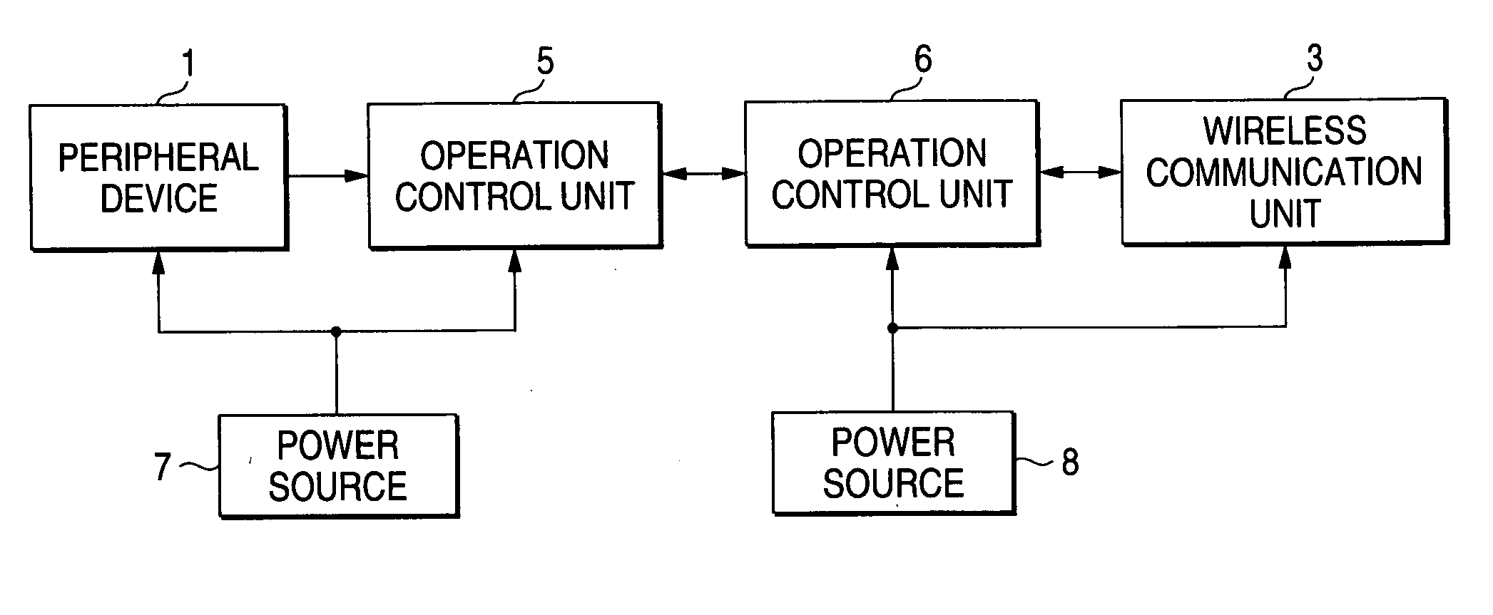
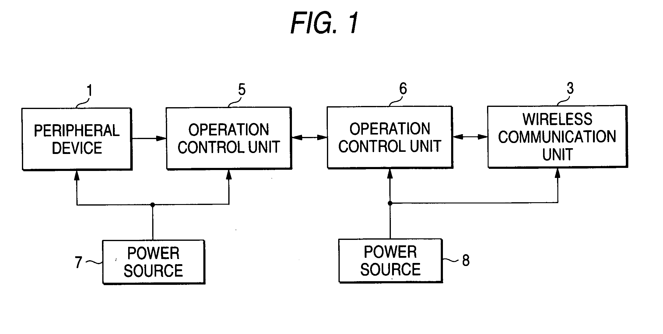
[0029]FIG. 1 is a block diagram showing a first embodiment of an electronic device according to the invention. In FIG. 1, the electronic device of the embodiment has a peripheral device 1 such as an external memory or a sensor; an operation control unit 5 such as CPU for executing an application; a wireless communication unit 3 for performing communication with the outside through a wireless network; an operation control unit 6 such as CPU for executing the control of the wireless communication unit 3 and the transmission / reception of data; a power source 7 for supplying electric power to the peripheral device 1 and the operation control unit 5; and a power source 8 for supplying electric power to the operation control unit 6, and the wireless communication unit 3.

[0030] In the embodiment, the peripheral device 1, the operation control unit 5 and the power source 7 constitute an application processing unit, and the wireless communication unit 3, operation control unit 6 and the pow...

second embodiment

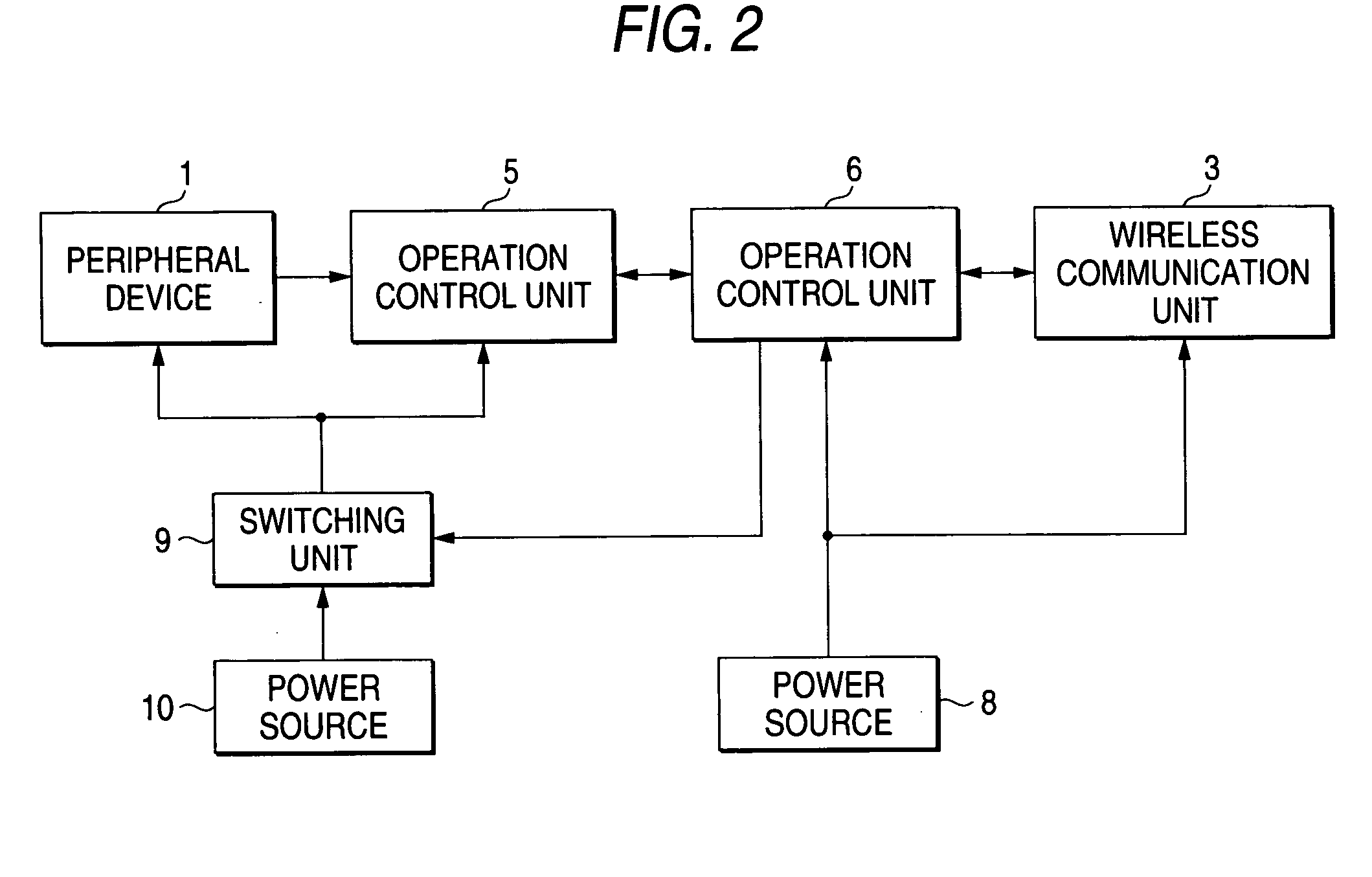
[0038]FIG. 2 is a block diagram showing a second embodiment of an electronic device according to the invention. In FIG. 2, the electronic device of the embodiment has the peripheral device 1; the operation control unit 5; a power source 10 for supplying electric power to the peripheral device 1 and the operation control unit 5; a switching unit 9 such as a switch or relay for controlling supply of the electric power from the power source 10; the operation control unit 6; the wireless communication unit 3; and the power source 8. Since the peripheral device 1, the wireless communication unit 3, the operation control unit 5, the operation control unit 6, and the power source 8 are same with those shown in FIG. 1, explanation regarding those are not given in the embodiment.

[0039] In the embodiment, the peripheral device 1, the operation control unit 5, the switching unit 9 and the power source 10 constitute an application processing unit, and the wireless communication unit 3, operati...


PUM


Abstract

An electronic device includes a communication unit which performs transmission/reception of data through a wireless network, and an application processing unit which executes an application processing. While the application processing is not required, the application processing unit is in a sleep state or a stand-by state.

Description

CROSS-REFERENCE TO RELATED APPLICATIONS [0001] This application is based upon and claims the benefit of priority from the prior Japanese Patent Applications No. 2004-111020, filed on Apr. 5, 2004, the entire contents of which are incorporated herein by reference. BACKGROUND OF THE INVENTION [0002] 1. Field of the Invention [0003] This invention relates to an electronic device for performing communication with the outside through a wireless network, and especially an electronic device capable of reducing power consumption. [0004] 2. Description of the Related Art [0005] The following documents are referred to as related art of an electronic device for performing communication with the outside through a wireless network. [0006] JP-A-08-084111 and JP-A-2002-050998 are referred to as the related art. [0007]FIG. 3 is a block diagram showing an example of such an electronic device for performing communication with the outside through a wireless network. In FIG. 3, the electronic device ha...

Claims


Application Information

Patent Timeline
Patent Type & Authority Applications(United States)
IPC IPC(8): H04M1/73H04W52/02H04B1/38G06F1/32H04B7/00H04M3/42H04B1/16
CPCH04M2250/12Y02D70/00H04W52/0235Y02D30/70
Inventor YAMAJI, MASATO
Owner YOKOGAWA ELECTRIC CORP
Why Eureka
Try Eureka