Case with hinged lid

Inactive Publication Date: 2005-10-13
HITACHI LTD
View PDF3 Cites 94 Cited by
  • Summary
  • Abstract
  • Description
  • Claims
  • Application Information

AI Technical Summary

Benefits of technology

[0010] According to the present invention, the seal can be compressed between the case body and the lid perpendicularly to the joining surface of the case body and the lid is restrained from dislocation relative to the case body. Consequently, the seal can be prevented from twisting or jamming and is able to seal the joint of the case body and the lid satisfactorily. Accordingly, the waterproofing ability is improved.
[0011] Since any lid fixing screw does not need to be connected to the hinge pin, the hinge pin needs to have a diameter and strength enough only to hold the lid. Therefore, th

Problems solved by technology

Consequently, a part of the seal nearer to the hinge cannot be compressed perpendicularly to the end surface of the case body, i.e., a contact surface of the case body with which the lid comes into close contact, and hence, in the seal, a possibility of not exercising an original waterproof function properly exists due to twisting or jamming.
However, since the lid is fixed to the case body by the screw connected to the hinge and the movement (stroke) of the lid is dependent on the degree of screwi

Method used


Image

  • Case with hinged lid
  • Case with hinged lid
  • Case with hinged lid

Examples


Embodiment Construction

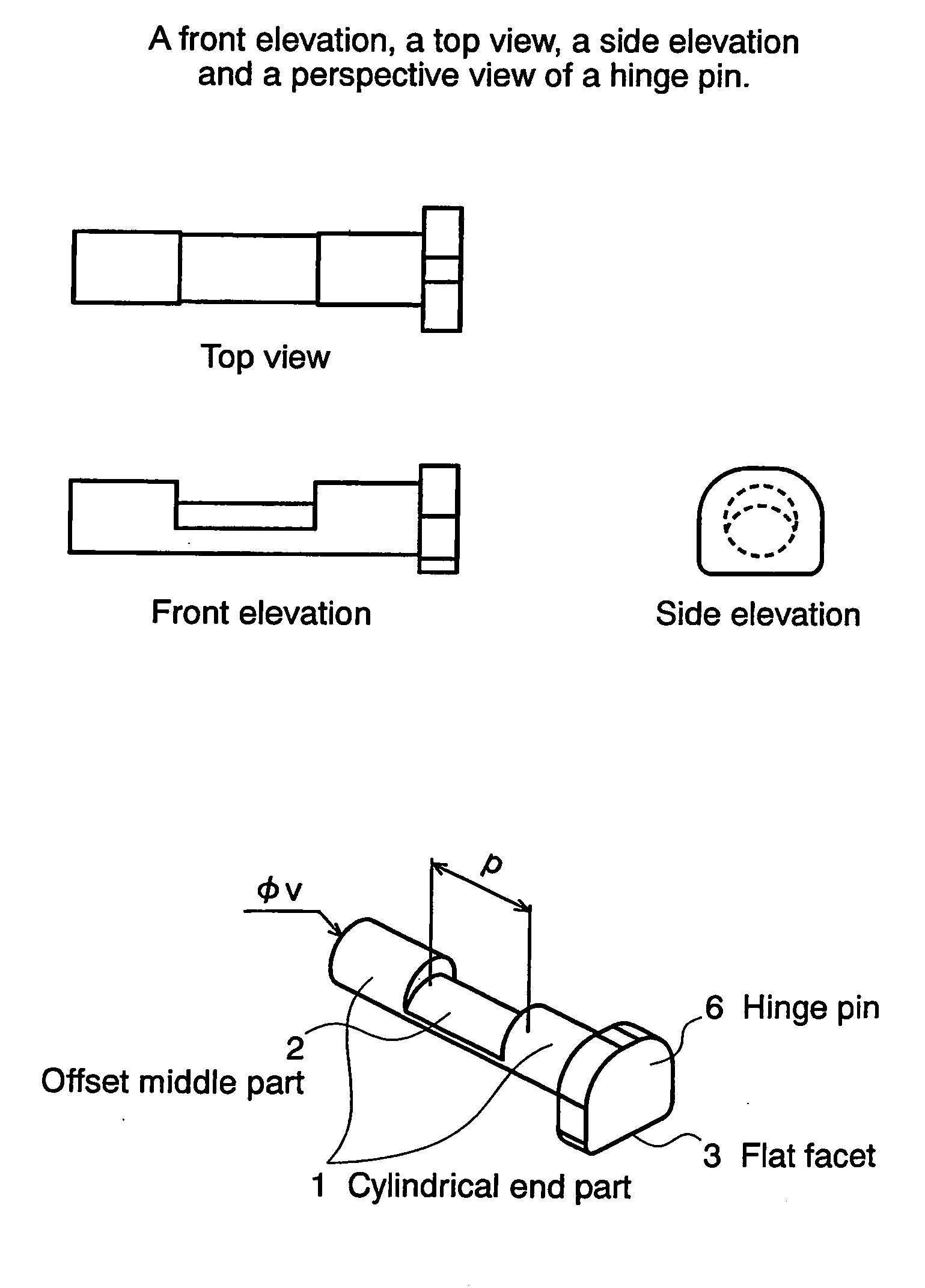
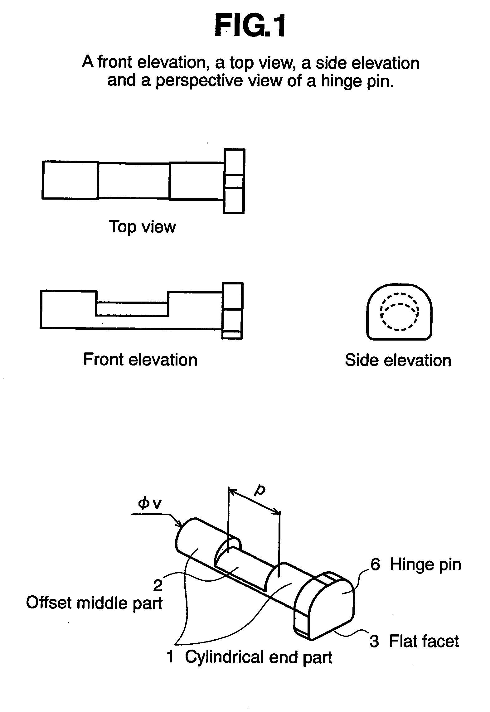
[0029] The basic constitution of the present invention will be described with reference to FIGS. 1 to 4. FIG. 1 is a perspective view of a hinge pin 6, which is a principal structural component of a case in a preferred embodiment according to the present invention. The hinge pin 6 has opposite cylindrical end parts 1, an offset middle part 2 extending between the cylindrical end parts 1, and a head 3 formed integrally with one of the cylindrical end parts 1 and having a flat facet. A groove is defined by the inner end surfaces of the cylindrical end parts 1 and the offset middle part 2. The flat facet of the head restrains the hinge pin 6 from rotating during opening and closing operations of the lid.

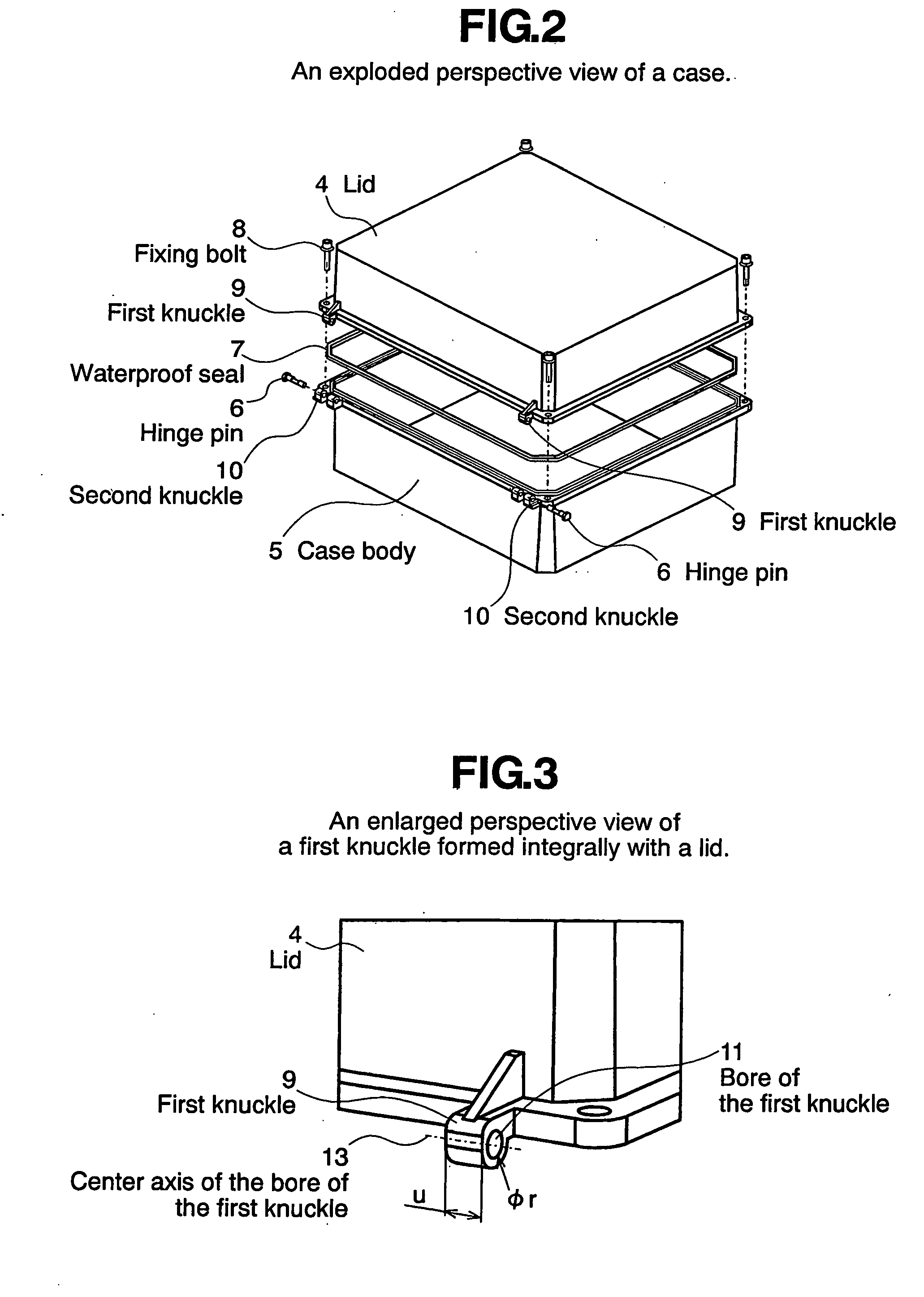
[0030]FIG. 2 is an exploded perspective view of a case in a preferred embodiment according to the present invention provided with the hinges respectively including the hinge pins 6. The case has a lid 4, a case body 5 for holding a wiring board provided with electronic devices, hinges ...


PUM


Abstract

A case includes a case body, a lid, hinges supporting the lid on the case body and a waterproof seal placed on the joining surface of the case body. The lid can be turned for closing on the hinges so as to compress the waterproof seal perpendicularly to the joining surface of the case body. Each hinge is provided with a hinge pin having opposite cylindrical end parts and an offset middle part defining a groove together with the cylindrical end parts. The grooves of the hinges permit first knuckles formed integrally with the lid to sink therein so that the lid held with its joining surface parallel to the joining surface of the case body can be moved toward the case body perpendicularly to the joining surface of the case body to compress the waterproof seal perpendicularly between the joining surfaces of the lid and the case body. The hinge pin is restrained from coming off by the first knuckles when the first knuckles are engaged in the groove.

Description

CROSS-REFERENCES TO RELATED APPLICATIONS [0001] This application is related to and claims priority from Japanese Patent Application No. 2004-116332, filed Apr. 12, 2004, and is hereby incorporated by reference for all purposes. BACKGROUND OF THE INVENTION [0002] The present invention relates to a hinge for a waterproof electronic device holding case and, more particularly, to a hinge capable of improving the waterproofing ability of a waterproof seal placed between the open end of an electronic device holding case and a lid. [0003] A waterproof outdoor electronic device holding case proposed in JP 2002-134948 A or JP 10-308586 A has a case body and a lid connected to the case body by hinges. The lid is turned (pivots) on the hinge pins of the hinges for opening and closing. An electronic device holding case proposed in JP 10-117072 A or JP 2002-176272 A has a case body, a lid and a waterproof seal placed between the open end of the case body and the lid so as to be compressed betwee...

Claims


Application Information

Patent Timeline
IPC IPC(8): F16C11/04B65D43/16B65D51/04H05K5/03
CPCB65D43/165B65D2251/205E05D5/10E05D5/128E05D2005/102E05Y2900/602Y10T16/557
Inventor TAJIRI, TAKESHIKAMIMURA, OSAMUKIMURA, YASUSHI
Owner HITACHI LTD
Why Eureka
Try Eureka