Rocking doorstop

a door stop and rocking technology, applied in the field of door stops, can solve the problems of ineffective procedure, insufficient static frictional force f/sub>s to withstand load, and numerous drawbacks of the conventional wedge-type door stop that is commonly available in the ar

Inactive Publication Date: 2005-10-13
PENDERGRASS MICHAEL
View PDF14 Cites 19 Cited by
  • Summary
  • Abstract
  • Description
  • Claims
  • Application Information

AI Technical Summary

Benefits of technology

[0017] The present invention solves the slip problem associated with conventional wedge-type door stops. By way of example, and not of limitation, a door stop according to the present invention is disclosed that rocks to form a three-point contact with the door and a floor surface to direct the door's energy downward a

Problems solved by technology

However, the conventional wedge-type door stops that are commonly available in the art suffer from numerous drawbacks.
However, for many surfaces, the resulting static frictional force Fs is still insufficient to withstand load L.
In many situations, this procedure is ineffective.
As a result, the jamming procedure required by such conventional door stops is often difficult and time consuming to secure in place.
In addition, the resulting additional fo

Method used


Image

  • Rocking doorstop
  • Rocking doorstop
  • Rocking doorstop

Examples


Embodiment Construction

[0063] Referring more specifically to the drawings, for illustrative purposes the present invention is embodied in the apparatus generally shown in FIG. 2A through FIG. 13C. It will be appreciated that the apparatus may vary as to configuration and as to details of the parts, and that the method may vary as to the specific steps and sequence, without departing from the basic concepts as disclosed herein.

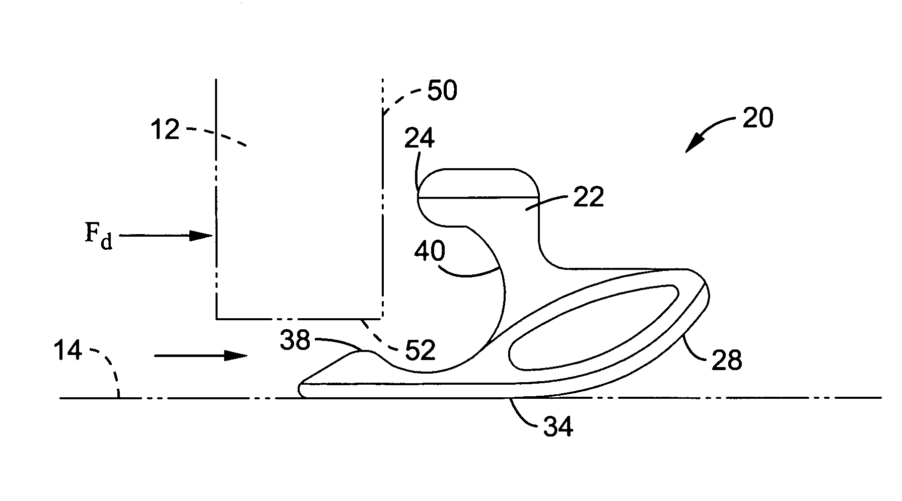
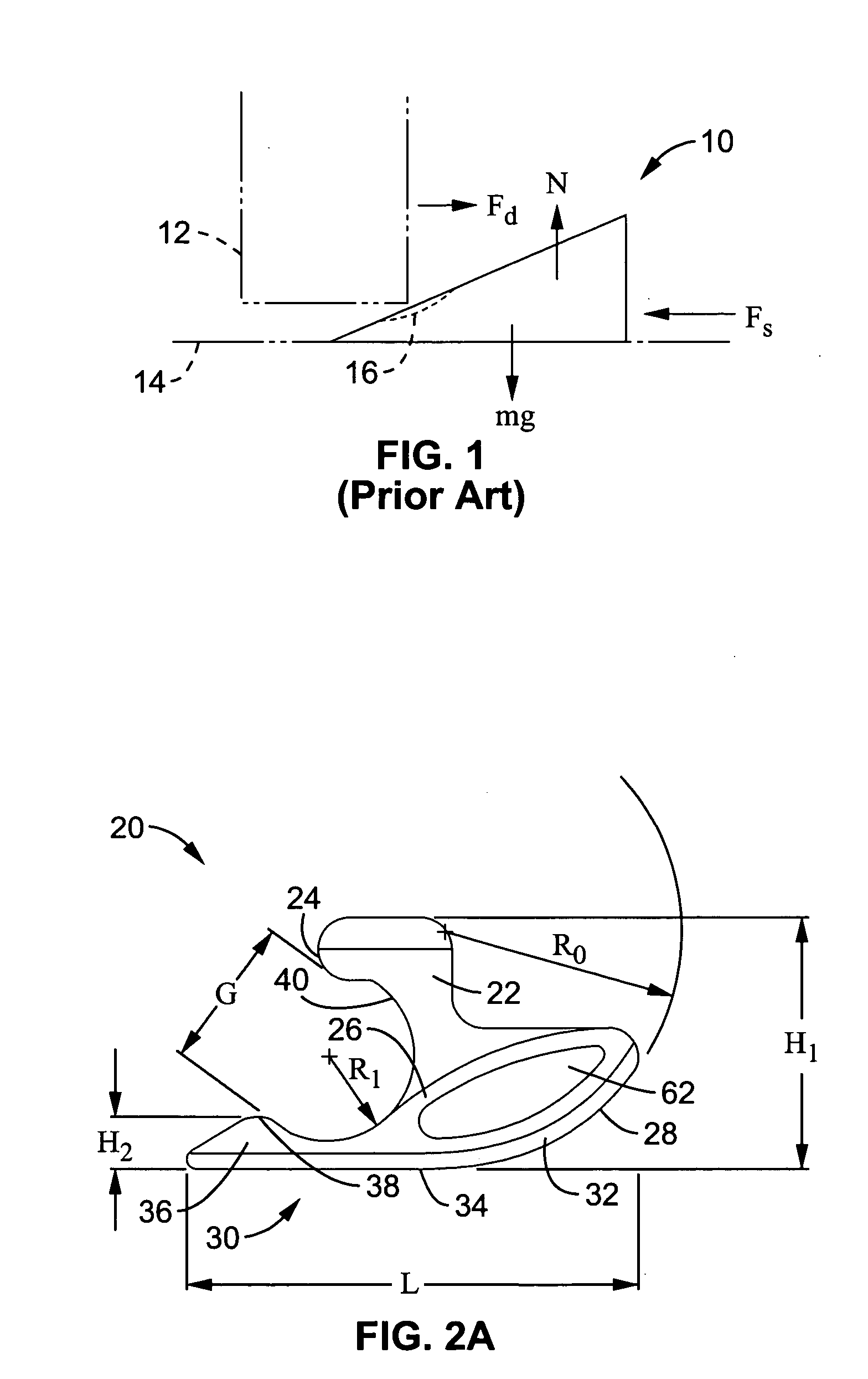
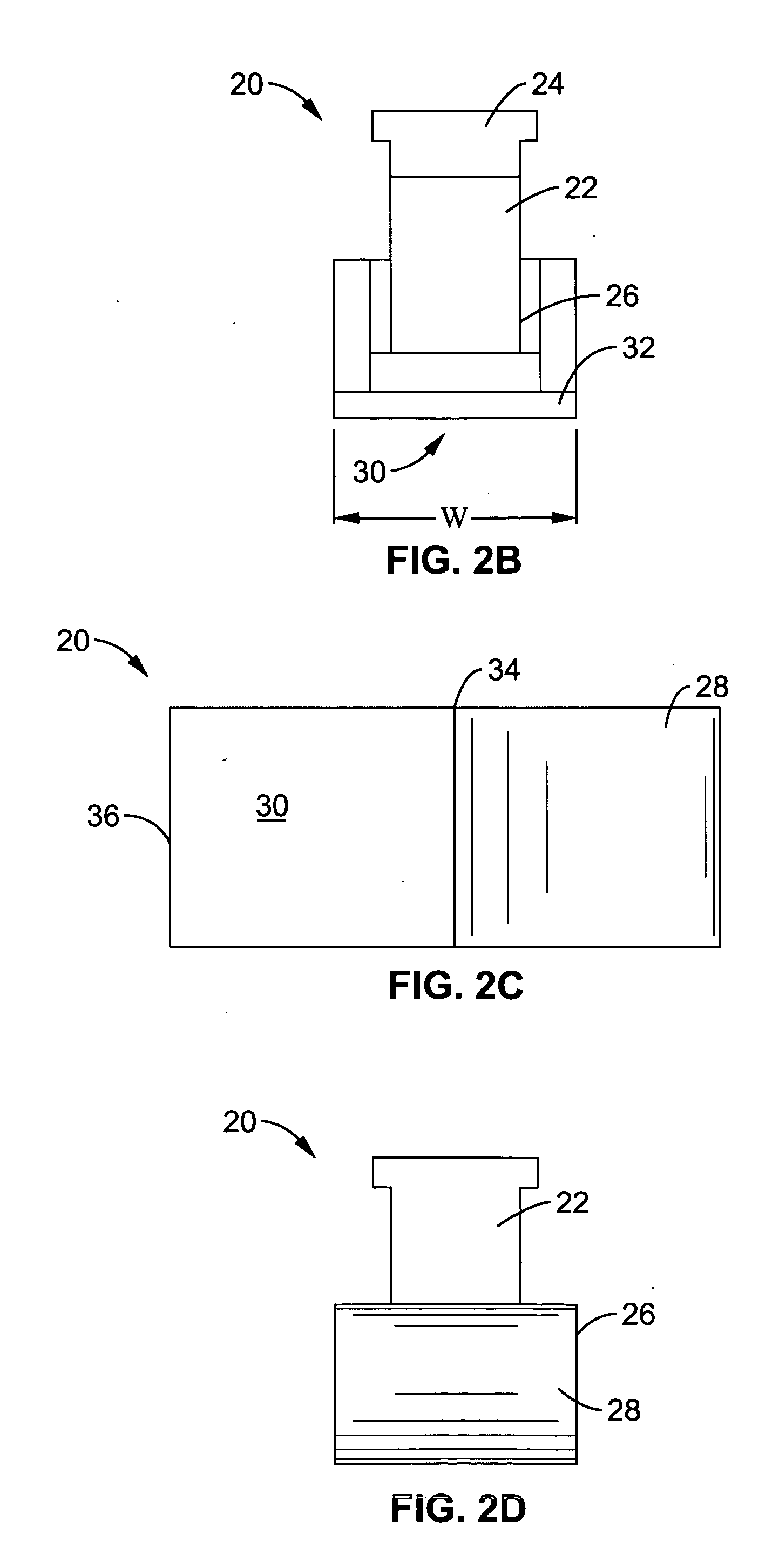
[0064] Referring to FIGS. 2A-D, a rocking doorstop 20 in accordance with the present invention is shown in side, front, bottom and rear views, respectively. Doorstop 20 has a body section 26 supporting lower arm 36 and upper arm 22. Arms 36 and 22 have contact points 38 and 24 respectively. Contact points 38 and 24 are separated by a curvilinear cutout 40 having an internal radius Ri defining an opening having gap dimension G. The internal radius Ri of curvilinear cutout 40 allows clearance of door 12 as shown in FIG. 3A-C.

[0065] Body section 26 and arm 36 integrally form lower sur...


PUM


Abstract

A rocking doorstop comprises a base portion having a lower surface for placement on a surface in proximity to a door. A first arm is coupled to the base portion such that the first arm is configured to engage a door as a result of motion of the door in a first direction. A second arm is also coupled to the base portion, wherein the second arm is configured to engage the door as a result of engagement of the first arm with the door. The engagement between the first and second arms and the door retains motion of the door in the first direction. The first arm is generally configured to engage the front surface of the door. The second arm is configured to engage the bottom surface of the door via a rocking motion created by the door engaging the first surface.

Description

CROSS-REFERENCE TO RELATED APPLICATIONS [0001] This application claims priority from U.S. provisional application Ser. No. 60 / 560,802 filed on Apr. 7, 2004, incorporated herein by reference in its entirety.STATEMENT REGARDING FEDERALLY SPONSORED RESEARCH OR DEVELOPMENT [0002] Not Applicable INCORPORATION-BY-REFERENCE OF MATERIAL SUBMITTED ON A COMPACT DISC [0003] Not Applicable NOTICE OF MATERIAL SUBJECT TO COPYRIGHT PROTECTION [0004] A portion of the material in this patent document is subject to copyright protection under the copyright laws of the United States and of other countries. The owner of the copyright rights has no objection to the facsimile reproduction by anyone of the patent document or the patent disclosure, as it appears in the United States Patent and Trademark Office publicly available file or records, but otherwise reserves all copyright rights whatsoever. The copyright owner does not hereby waive any of its rights to have this patent document maintained in secre...

Claims


Application Information

Patent Timeline
IPC IPC(8): E05B65/20E05C17/54E05C5/00
CPCE05C17/54Y10T292/73
Inventor PENDERGRASS, MICHAEL
Owner PENDERGRASS MICHAEL
Why Eureka
Try Eureka