

Device for fixing a housing, epecially a housing pertaining to a motor vehicle battery, to a carrier plate
- Summary
- Abstract
- Description
- Claims
- Application Information
AI Technical Summary
Benefits of technology
Problems solved by technology
Method used
Image

Examples
Embodiment Construction
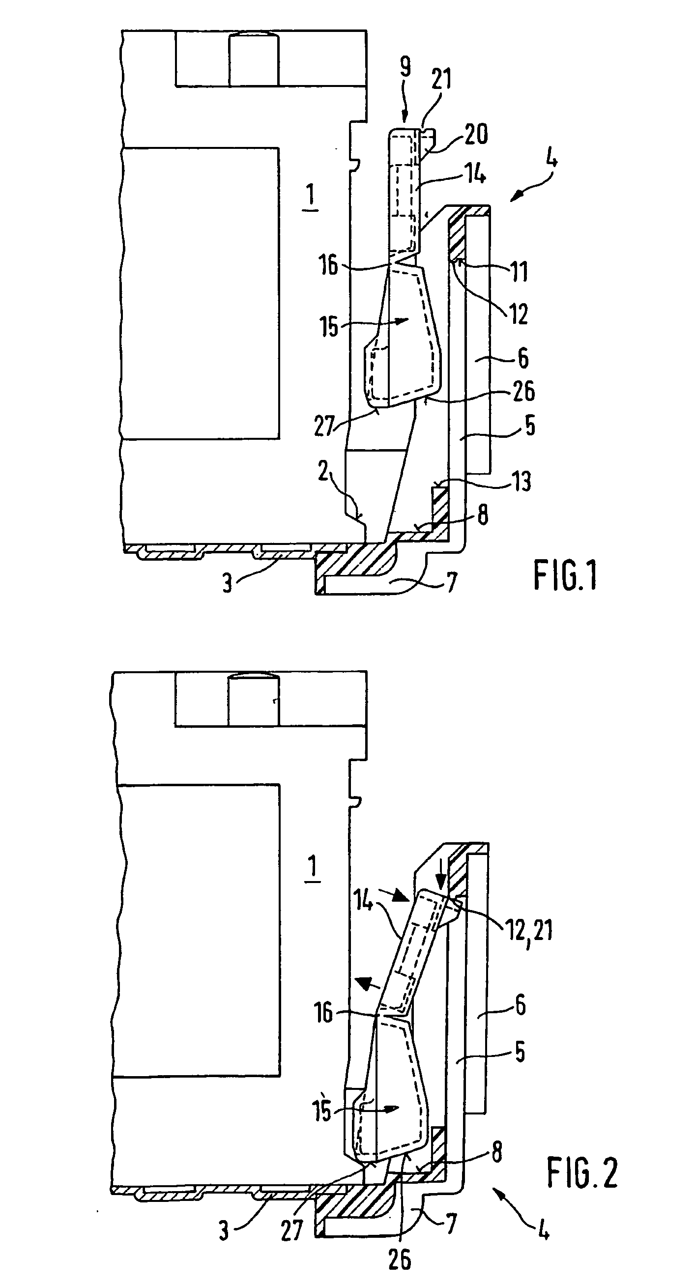
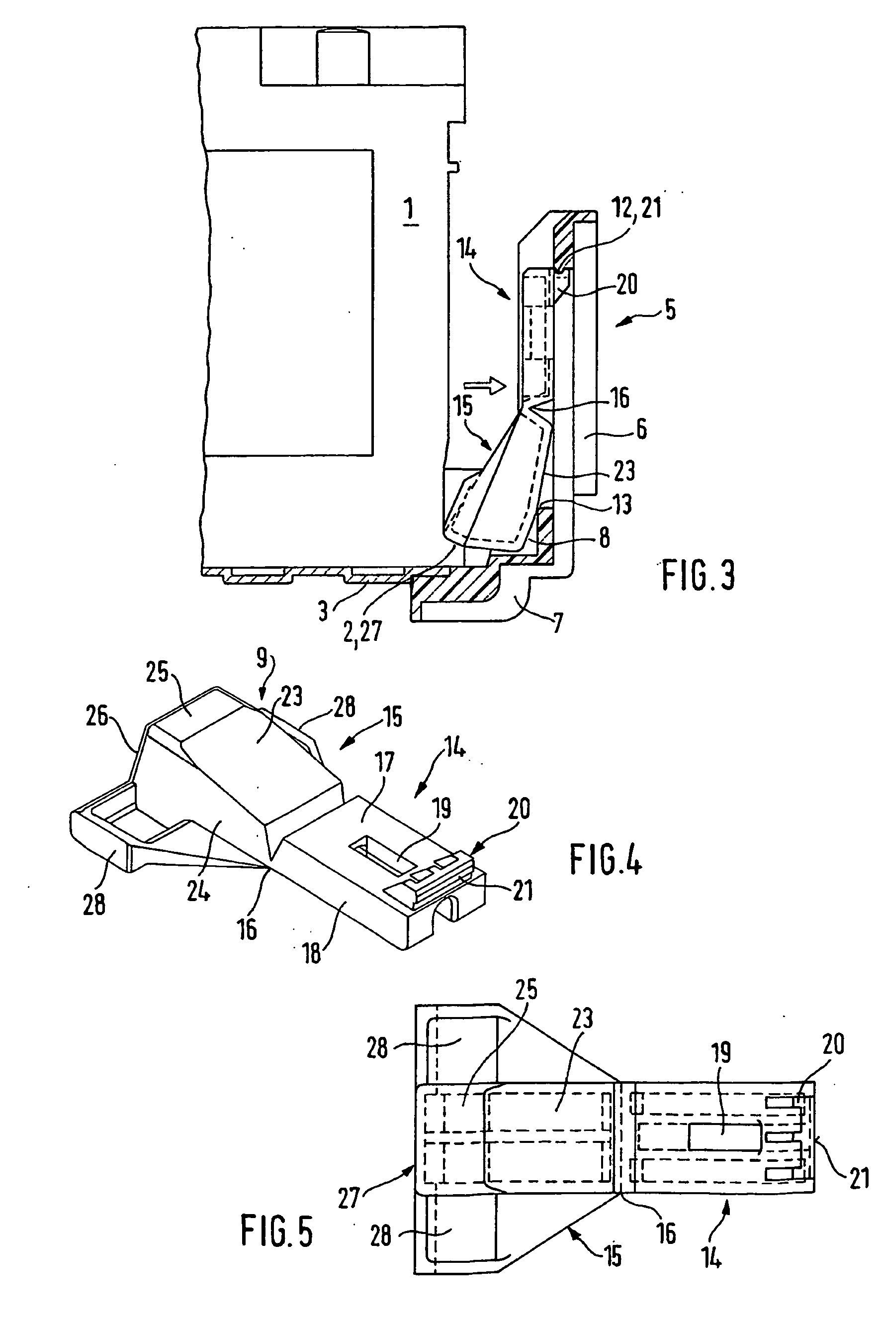
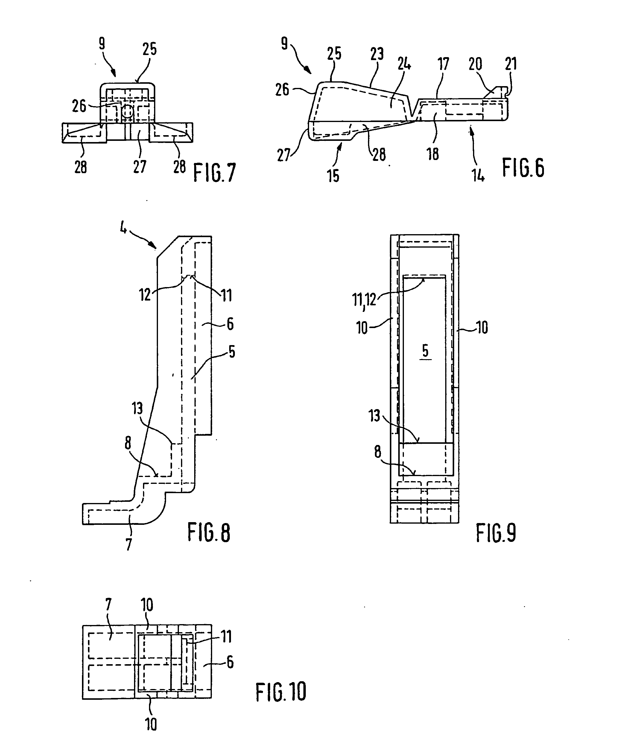
[0024]FIG. 1 shows schematically a part of the housing 1 of a motor-vehicle battery, which has, in a known way, a step 2, which is formed preferably with a slight slope, laterally across the base of the housing. The housing 1 rests on a carrier plate 3, which on this side projects past the housing 1. On this side of the carrier plate 3, there is a fixing bracket 4, which can be integrally molded with the carrier plate 3 or connected rigidly thereto in some other way. Extending from the fixing bracket 4, which is shown again separately in FIGS. 8-10, is a long vertical limb 5 parallel and at a distance to the side wall of the housing 1. A reinforcement rib 6 is preferably provided on its outer side. First of all, a shorter horizontal limb 7 is used for fixing plate 3 to the carrier and forms a right angle with the vertical limb 5 at least on the inside of the fixing bracket 4, so that here a horizontal contact surface 8 is produced for a separate fixing element 9, which, as described...
PUM
 Abstract
Description
Claims
Application Information