
Adaptive supply voltage body bias apparatus and method thereof

a supply voltage and body bias technology, applied in the direction of logic circuits, pulse generator details, pulse techniques, etc., can solve the problems of supply voltage dissipation or ineffective utilization, current leakage, and more leakag

Inactive Publication Date: 2005-10-13
ATI TECH INC
View PDF13 Cites 51 Cited by
  • Summary
  • Abstract
  • Description
  • Claims
  • Application Information

AI Technical Summary

Problems solved by technology

Inherent within the integrated circuit is potential for current leakage, wherein a supply voltage is dissipated or ineffectively utilized by the integrated circuit.
With the increase of nanometer technology, and the higher frequency of devices within an integrated circuit, more leakage is generated.
Thereupon, this generates multiple problems including effecting the speed or performance of an integrated circuit, increasing power consumption and leakage and requiring a greater amount of active power for a system.
Overall power consumption may be controlled using this approach, but does not provide for an efficient correlation between critical path devices, non-critical path devices and threshold voltages.
The ABB approach is limited because, among other things, it fails to optimize threshold voltage for all devices at the cost of seeking current leakage reduction for the overall system.
Although, the ASB approach is limited to one or more devices having a common threshold voltage.
Therefore, the ASB approach is significantly limited to applications in which all devices have the same threshold voltages.
In the current nanometer generation, the silicon has reached its physical limitations and computing device voltage leakage is exponentially increasing.
Therefore, the DVS approach and ABB approach are no longer used for future generations due to the cumulative effect of leakage and efficiency based on threshold voltage, respectively.
Furthermore, in the increase of devices on an integrated circuit, the ASB approach is limited based on the devices having multiple threshold voltages.

Method used


Image

  • Adaptive supply voltage body bias apparatus and method thereof
  • Adaptive supply voltage body bias apparatus and method thereof
  • Adaptive supply voltage body bias apparatus and method thereof

Examples


Embodiment Construction

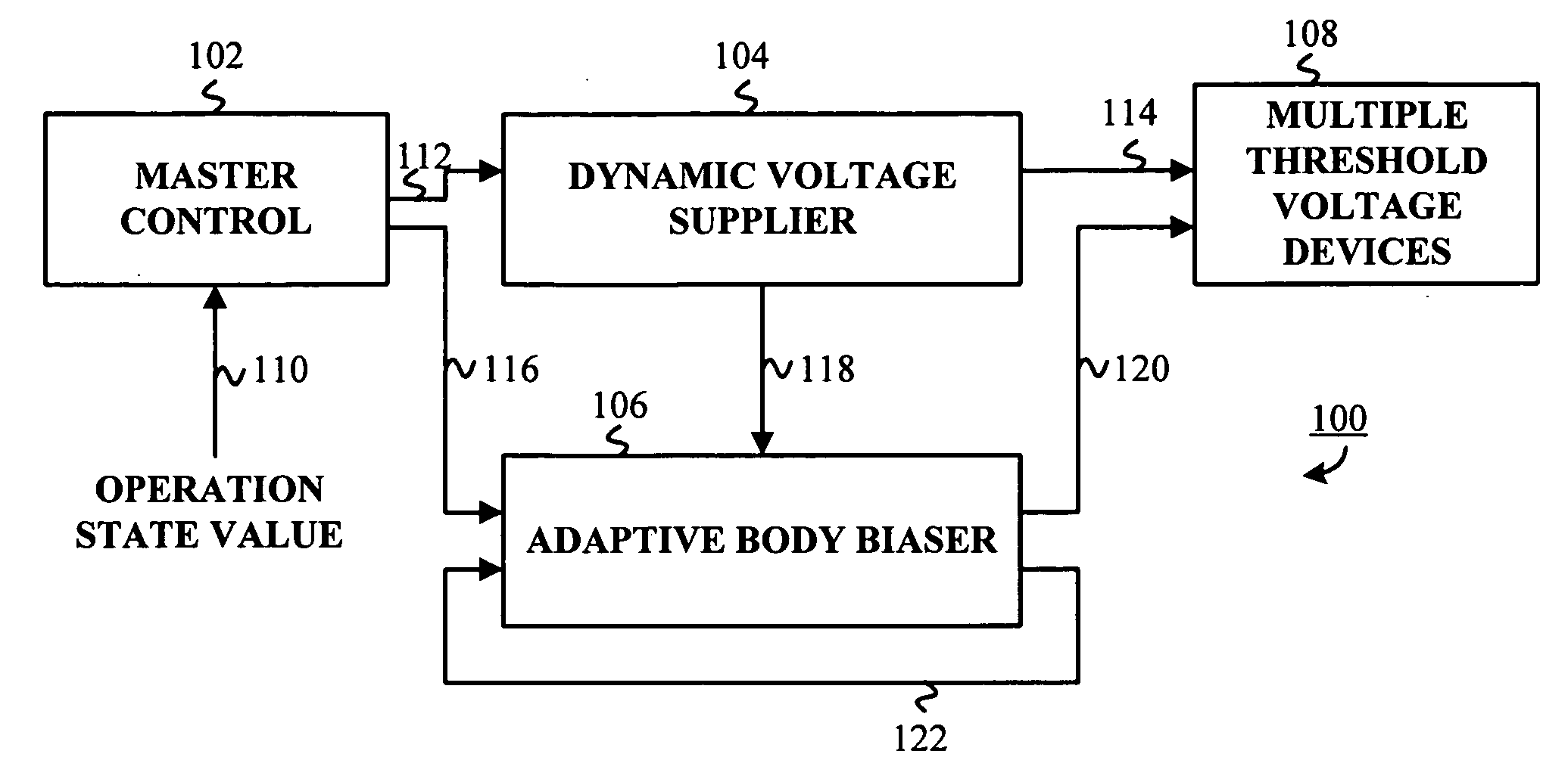
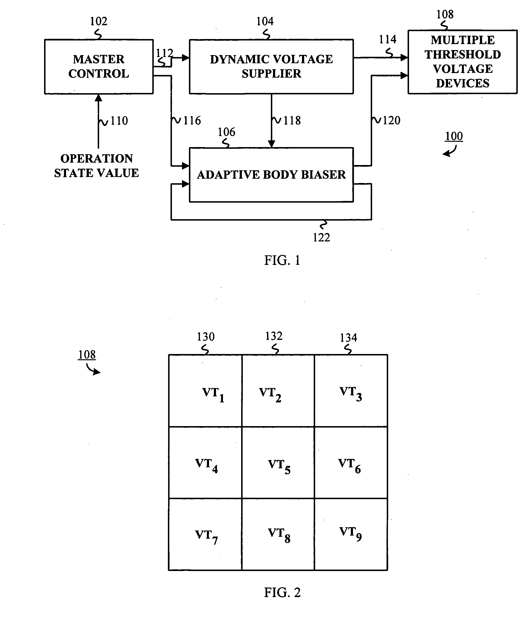
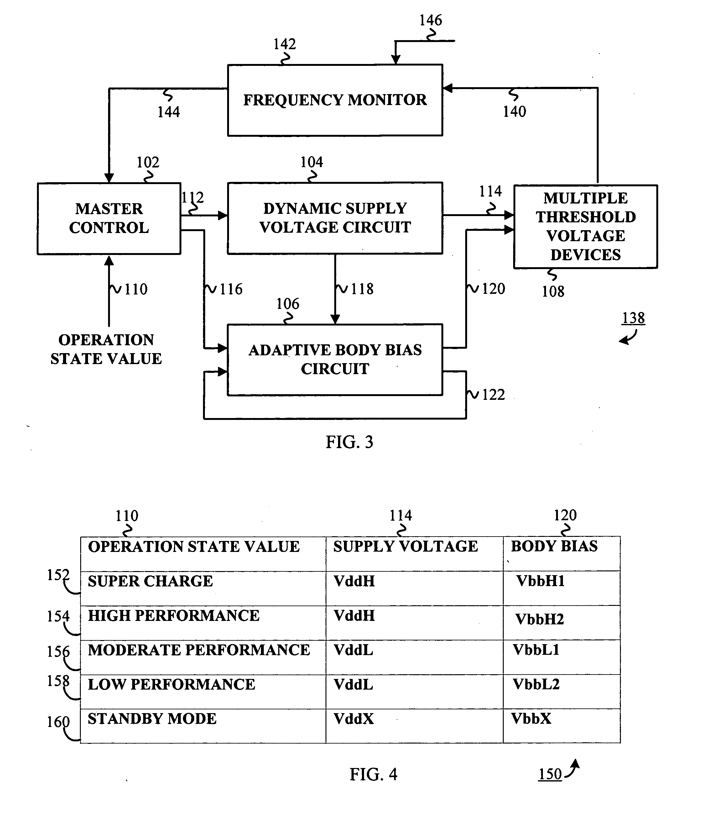
[0019] Generally, an adaptive supply voltage and body bias apparatus and method thereof includes a master controller including an operation state value. The master controller may be any suitable processing device disposed within hardware, software or combination thereof performing the below-noted functionality. An operation state value may be any type of indicator indicating a type of operations state, such as and not limited to a supercharge state, a high performance state, a moderate performance state, a low performance state, and a standby mode, wherein the states indicate the operations level of an integrated circuit.

[0020] The apparatus and method further includes a dynamic voltage supplier operably coupled to the master controller, the dynamic voltage supplier operative to receive a supply voltage indicator. The dynamic voltage supplier may be any suitable standard dynamic voltage supplier as recognized by one having ordinary skill in the art. The supply voltage indicator may...


PUM


Abstract

An adaptive supply voltage and body bias apparatus includes a master controller including an operation state value. The apparatus and method includes a dynamic voltage supplier coupled to the master controller operative to receive a supply voltage indicator. The apparatus and method includes an adaptive body biaser coupled to the master controller operative to receive a body bias indicator. Furthermore, the apparatus and method includes a plurality of computing devices each having one of a plurality of threshold voltages. The plurality of computing devices are operative to receive the supply voltage from the dynamic voltage supplier and a bias voltage from the adaptive body biaser for optimized power supply in conjunction with reduction of power leakage in view of the varying threshold voltage of the computing devices.

Description

FIELD OF THE INVENTION [0001] The present invention relates generally to power supply for an integrated circuit and more specifically, to optimizing integrated circuit power consumption through adjustable supply voltage and biasing. BACKGROUND OF THE INVENTION [0002] In a typical processing unit, such as an integrated circuit, voltage supply is an important component for efficient operations. Inherent within the integrated circuit is potential for current leakage, wherein a supply voltage is dissipated or ineffectively utilized by the integrated circuit. With increased current leakage, there is a direct reduction in performance of the integrated circuit as well as a direct increase in power requirements. [0003] The integrated circuit is typically composed of multiple computing devices, such as one or more compilations of components for computing a specific function. For example, a device may consist of a series of gates and connections for allowing a specific calculation, such as fo...

Claims


Application Information

Patent Timeline
Patent Type & Authority Applications(United States)
IPC IPC(8): H03K19/00H03K3/01
CPCH03K19/0013H03K19/0016
Inventor KIN LAW, OSCAR MING
Owner ATI TECH INC
Learn More