Marine LED lighting network and driver

a led lighting and led lighting technology, applied in the field of system and method of illuminating an environment, can solve the problems of long time-consuming and laborious, dangerously hot fixture operating temperature, and expensive bulb burn-out, and achieve the effect of simple addressing

Inactive Publication Date: 2005-10-13
INTEGRATED ILLUMINATION SYST
View PDF13 Cites 105 Cited by
  • Summary
  • Abstract
  • Description
  • Claims
  • Application Information

AI Technical Summary

Benefits of technology

[0012] The expansion module offers integration to computers with at least one of a touch screen, membrane switch, keypad, keyboard, switch, mouse, or dimmer as a

Problems solved by technology

The lighting system has long been plagued by energy inefficiencies, unpredictability, expensive bulb burn-outs, dangerously hot fixture operating temperatures, and simplistic means of con

Method used


Image

  • Marine LED lighting network and driver
  • Marine LED lighting network and driver
  • Marine LED lighting network and driver

Examples


Embodiment Construction

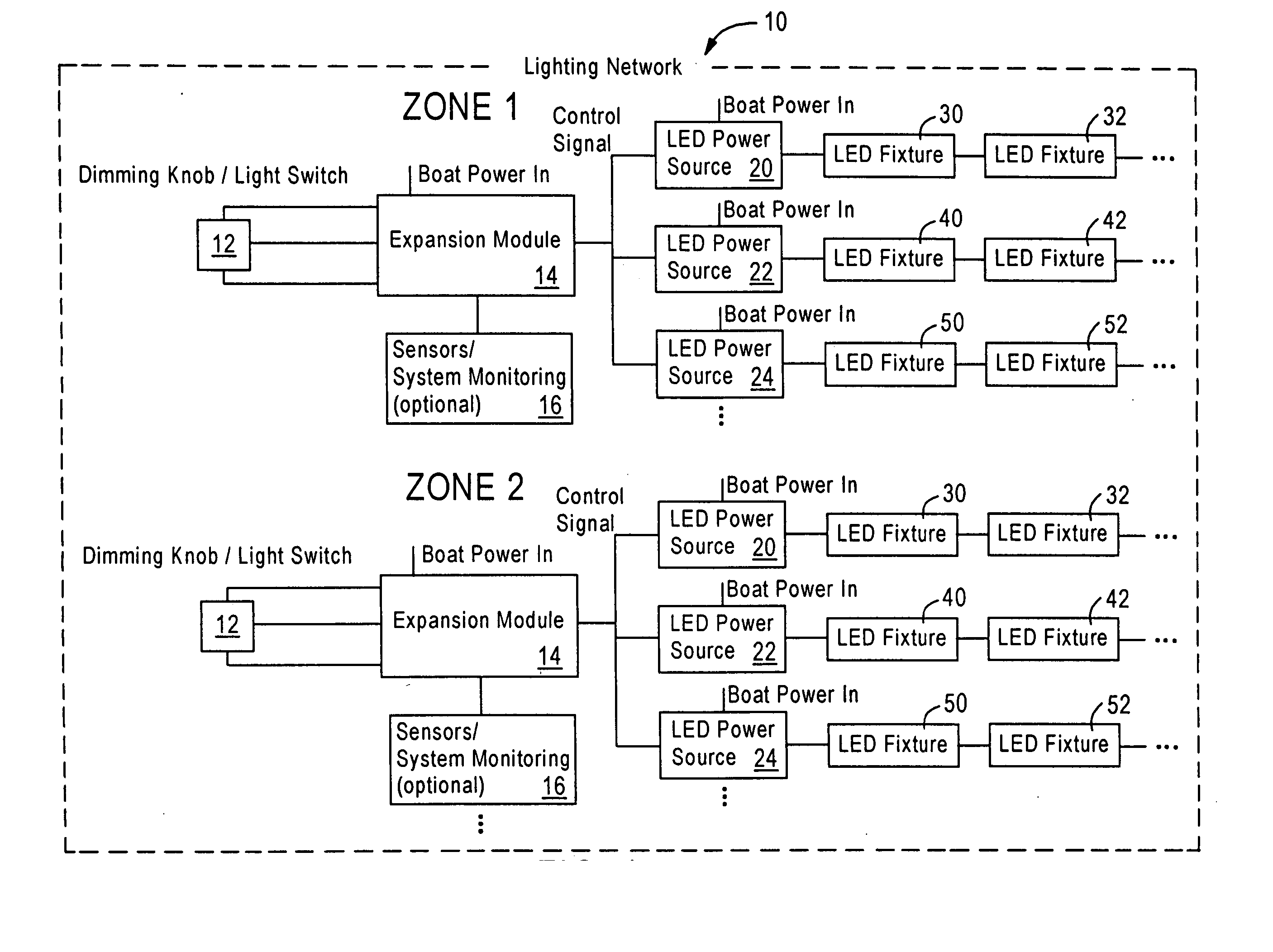
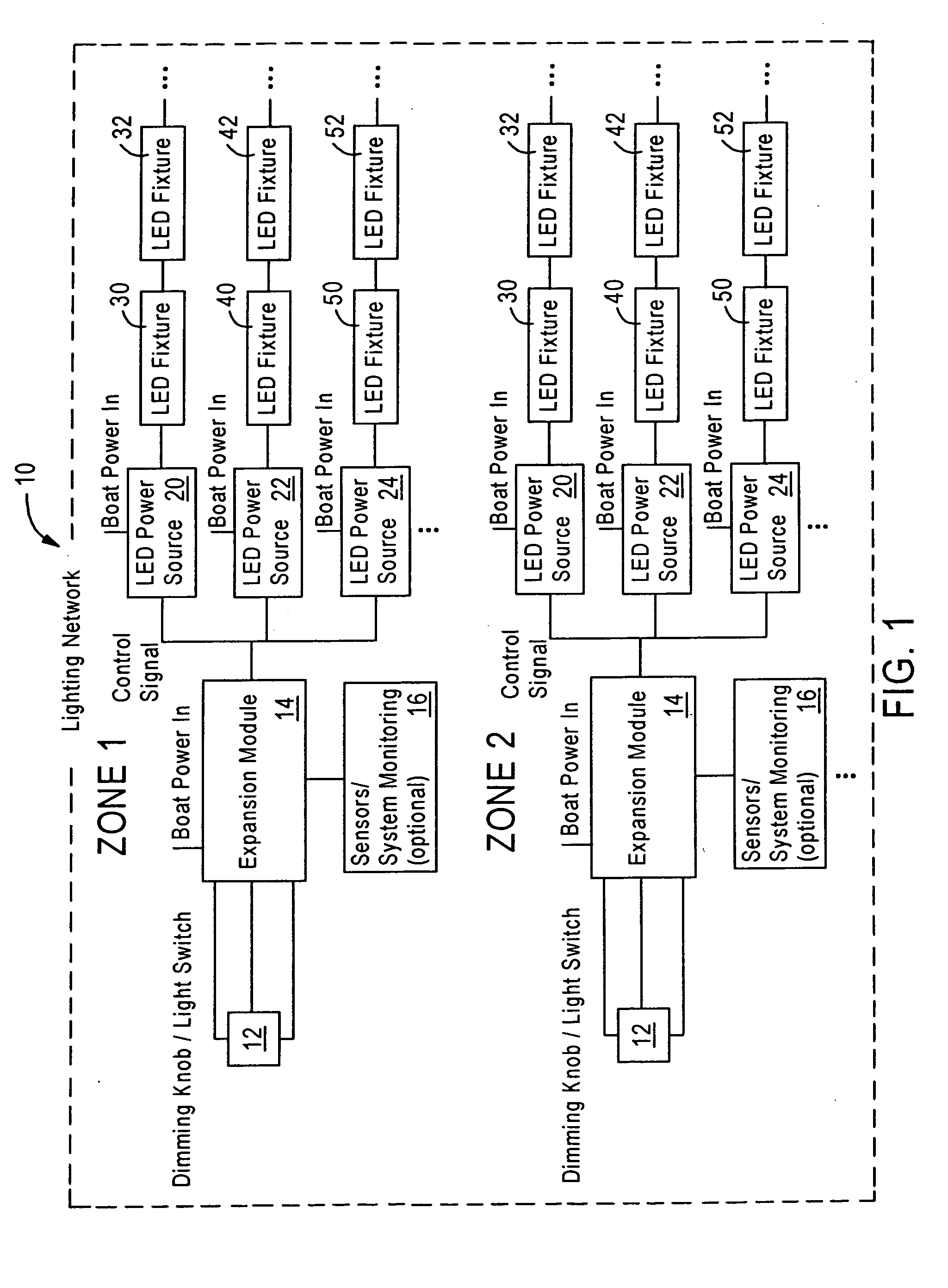
[0027] A lighting network is depicted in FIG. 1 having zones 1 and 2. As depicted in FIG. 1, Zone 2 has the identical configuration of zone 1, although this is for illustrative purposes only. The present invention can combine the embodiments depicted in FIGS. 1-3. Also, the FIG. 1 embodiment, for example, can use other LED power sources.

[0028] In FIG. 1, a conventional Light Switch / Dimming Knob 12 is used to control an expansion module 14. This may be done a number of ways including utilizing a control voltage that the expansion module 14 references. Optional sensor system monitoring 16 is connected to the expansion module 14 for monitoring the expansion module's 14 environment. The expansion module 14 generates a control signal that controls the output of each of the LED power sources 20, 22, 24. Each LED power source 20, 22, 24 provides a constant output to each LED fixtures 30, 40, 50 to which it supplies power. The number of LED power sources is not limited to three. Each power...


PUM


Abstract

The method and system described herein is designed to illuminate, control, and network LEDs lights used onboard marine platforms. Disclosed is a method and system for illuminating a portion of a marine vessel or platform. A lighting system is controlled by generating a lighting signal for controlling plurality of LED lights placed in a plurality of positions within the vessel. An LED space is designed to illuminate LEDs (or other lighting fixtures) by providing a controller for providing constant current source via a switching regulator configuration.

Description

RELATED APPLICATIONS [0001] The present application is based on, and claims priority from U.S. Provisional Application No. 60 / 560,294, filed Apr. 8, 2004, the disclosure of which is hereby incorporated by reference herein in its entirety.FIELD OF THE INVENTION [0002] The present invention is directed to a system and method of illuminating an environment and more particularly to an environment such as on a marine vessel. The present invention is also related to an illumination system using LEDs, and a driver having a controller which provides a constant current source to the LEDs. BACKGROUND OF THE INVENTION [0003] One of the slowest moving industries in regard to adopting new technologies, the boating industry is years away from being regarded as high tech when compared to automotive and aviation industries. Many traditional systems that were originally specified 30 years ago are still being specified today on brand new vessels. The lighting system has long been plagued by energy in...

Claims


Application Information

Patent Timeline
IPC IPC(8): B63B45/04B63B45/06F21V9/16H05B44/00
CPCB63B45/04B63B45/06F21W2101/04H05B33/0863H05B33/0842H05B33/0857F21W2111/04F21W2107/20H05B45/20H05B47/115Y02B20/40H05B45/375H05B45/395H05B45/325Y02B20/30
Inventor ZAMPINI, THOMAS LAWRENCEZAMPINI, THOMAS LAWRENCE IIZAMPINI, MARK ALPHONSE
Owner INTEGRATED ILLUMINATION SYST
Why Eureka
Try Eureka