
Power distributor

a technology of power distributor and module, applied in the field of module power distributor, can solve the problems of disadvantageous repair and subsequent changes in the assembled state of the power distributor, particularly laborious assembly of such a power distributor, etc., and achieve the effect of facilitating maintenance or repair and detecting easily and reliably

Active Publication Date: 2018-09-06
ELLENBERGER & POENSGEN GMBH
View PDF0 Cites 3 Cited by
  • Summary
  • Abstract
  • Description
  • Claims
  • Application Information

AI Technical Summary

Benefits of technology

The power distributor described in this patent is designed for communication and signaling applications and is connected in a modular way, which makes it easy to adapt and flexibly used in an electrical system. It has a low wiring and circuitry cost and is particularly useful for detecting wire breaks or defective components in the module package, simplifying maintenance or repair. The first controller assigns addresses to the modules, allowing for simple addressing of the second controller and making it possible to allocate addresses even if a module is subsequently equipped with a circuit breaker. The determined position can be made available to or signaled to a user, improving maintenance or repair of the power distributor.

Problems solved by technology

Thus, the assembly of such a power distributor is particularly labor intensive.
Furthermore, the switching system formed by such a power distributor is relatively hard to navigate due to the single wiring, which makes repair and subsequent changes in the assembled state of the power distributor disadvantageous.

Method used


Image

  • Power distributor
  • Power distributor
  • Power distributor

Examples


Embodiment Construction

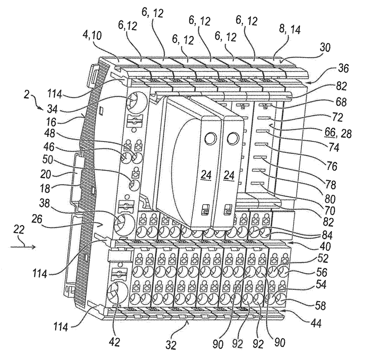
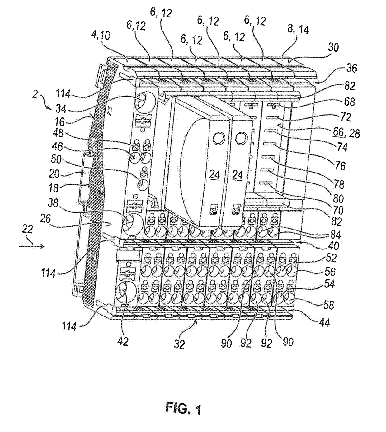
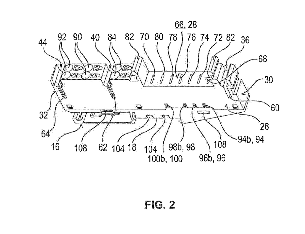
[0053]As (power distribution) modules, the power distributor 2 shown in FIG. 1 comprises a supply module 4, six connection modules 6 and a signal module 8, wherein the connection modules 6 are shown individually in FIG. 2. Each module 4, 6, 8 includes a housing 10, 12 or 14 that is separate, i.e., separated from the other modules 4, 6, 8. Each module 4, 6, 8 is designed in the form of a modular device and accordingly has a groove-like slot 18 on the rear panel of a housing 16, with which the respective module 4, 6, 8 can be snapped onto a supporting rail 20 for assembly.

[0054]The profile direction of this slot 18—and, accordingly, also the profile direction of the supporting rail 20 corresponding to this slot 18 in the assembled state—define a row direction 22 along which the modules 4, 6, 8 are lined up together. In the exemplary embodiment shown in FIG. 1, two circuit breakers 24 are arranged at a respective connection module 6, inside the (module) package formed of the modules 4,...


PUM


Abstract

A power distributor having a first controller and having a number of connection modules which are connected thereto and are intended to be mounted on a supporting rail. The connection module has a number of lateral coupling contacts for the electrical and / or signalling contact connection to at least one further connection module which is attached or can be attached to the particular connection module, wherein a base resistor is connected in each case between two coupling contacts inside the module in such a manner that the base resistors of the attached connection modules form a resistor chain which is connected in series. The connection modules are each equipped or can be equipped with an actuatable circuit breaker. The circuit breakers have a second controller inside the circuit breaker for recording a voltage dropped across the respectively associated base resistor.

Description

[0001]This nonprovisional application is a continuation of International Application No. PCT / EP2016 / 068462, which was filed on Aug. 2, 2016, and which claims priority to German Patent Application No. 10 2015 221 899.6, which was filed in Germany on Nov. 6, 2015, and which are both herein incorporated by reference.BACKGROUND OF THE INVENTIONField of the Invention[0002]The present invention relates to a modular power distributor intended for direct mounting on a supporting rail, comprising a number of power distribution modules, in particular in the form of modular devices. The invention further relates to a method for operating such a power distributor.Description of the Background Art[0003]A power distributor can be understood as an electrical installation having one or more electric load circuits to which a current is supplied from a main line. In the context of the power distributor, safety mechanisms are provided which secure each load circuit against overload or a short circuit....

Claims


Application Information

Patent Timeline
Patent Type & Authority Applications(United States)
IPC IPC(8): H02B1/052G05B15/02H02B1/20H02B1/056
CPCH01H71/02H02B1/056G05B15/02H02B1/052H02B1/205G05B19/0421G05B19/0425G05B2219/21028G05B2219/21008G05B2219/25117E04B2/88E04F13/0803E04F21/18H02J13/00012G01R31/54G01R31/52H02J13/00034
Inventor ASANZA MALDONADO, DIEGO FERNANDO
Owner ELLENBERGER & POENSGEN GMBH
Learn More