Replacement illumination device for a miniature flashlight bulb

Inactive Publication Date: 2005-10-13
J BAXTER BRINKMANN INT +1
View PDF13 Cites 61 Cited by
  • Summary
  • Abstract
  • Description
  • Claims
  • Application Information

AI Technical Summary

Benefits of technology

[0007] The principal advantage of such an illumination device is that the advantages of solid state illumination can be more quickly offered to consumers for a variety o...

Problems solved by technology

However, to accomplish the retrofit, space for ...

Method used


Image

  • Replacement illumination device for a miniature flashlight bulb
  • Replacement illumination device for a miniature flashlight bulb
  • Replacement illumination device for a miniature flashlight bulb

Examples


Embodiment Construction

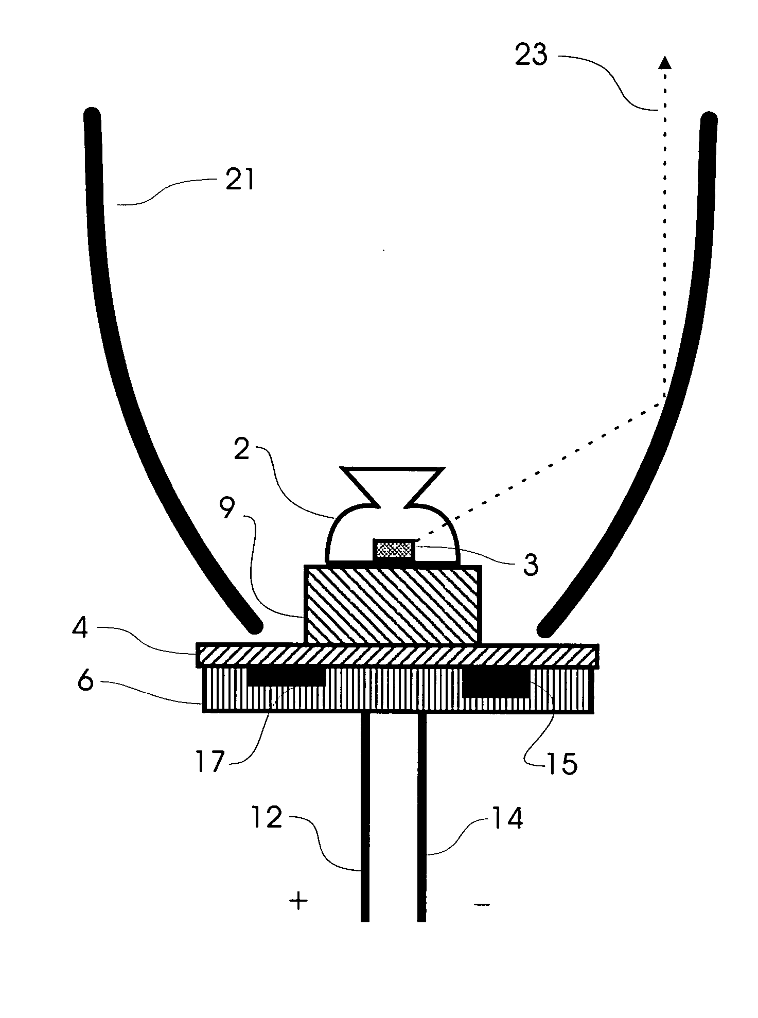
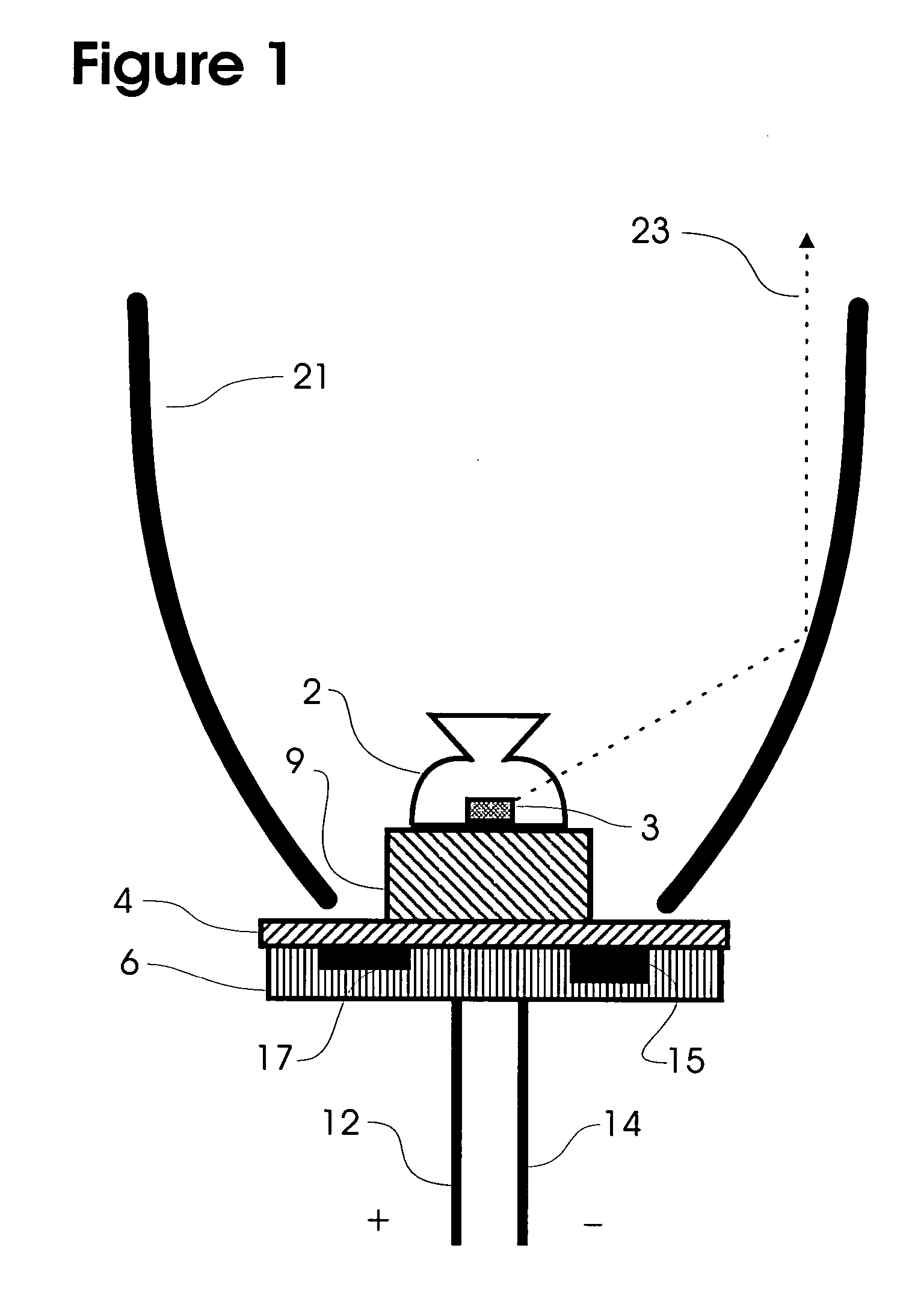
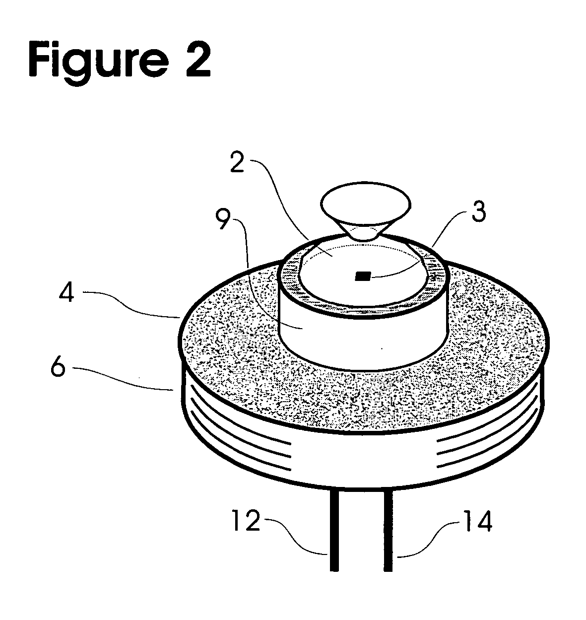
[0039] A perspective view of a preferred physical form for this invention is shown in FIG. 2. A cross-section of FIG. 2 appears as FIG. 1.

[0040] In FIG. 1, the standard light bulb power connector is shown as pins 12 and 14, respectively conductively connected to the positive and negative power source of the flashlight (presumably batteries). The light emitter 3 typically would be an LED chip embedded in a transparent plastic lens 2 and a driving circuit embedded in a module. (Of course, potentially more than one light emitting chip could be used, perhaps to simulate white light with multiple chips each emitting a different wavelength.)

[0041] Also in FIG. 1, the transparent lens 2 of the light emitter preferably is so shaped that it refracts a majority of the emitted light laterally toward the reflector 21. Reflector 21 would ideally have the shape of a portion of a paraboloid, with the light-emitting chip 3 on the centerline (axis of revolution) near the focal point of the parabol...


PUM

PropertyMeasurementUnit
Poweraaaaaaaaaa
Volumeaaaaaaaaaa
Shapeaaaaaaaaaa

Abstract

Disclosed is a method and apparatus for providing a solid state light emitter and driving circuitry integrated into a component module that will retrofit common incandescent light bulb applications. The disclosed embodiment is directed to the retrofitting of small flashlights using miniature bulbs, such as the Mini Maglite®. Because the emitter and driving circuitry cannot readily fit within the envelope of the bulb being replaced, the volume occupied by the module needs to be acquired from within the flashlight's interior, such as from part of the volume occupied by the reflector. In that case, the invention includes a replacement reflector supplied with the module. The invention provides that no original functionality of the flashlight is sacrificed. Consideration is also given to the conduction of heat from the light emitter and module.

Description

CROSS-REFERENCE TO RELATED APPLICATIONS [0001] This non-provisional U.S. patent application is a continuation-in-part based on application Ser. No. 10 / 820,930, filed Apr. 8, 2004, and claims the benefit of the prior application.FIELD OF INVENTION [0002] This invention relates to a solid state replacement for a miniature bulb in a flashlight. BACKGROUND [0003] Non-provisional patent application Ser. No. 10 / 820,930, filed on Apr. 8, 2004, described an invention which can replace incandescent light bulbs with more efficient light emitters such as light-emitting diodes (LEDs). The Background section of that patent application provided the justification for doing so, and it is incorporated herein by reference. [0004] However, the description of the embodiment of that invention of that prior patent application and its claims prescribed circuitry which fit within the 3-d spatial envelope defined by the incandescent bulb, which is replaced by an instance of that prior invention. Furthermore...

Claims


Application Information

Patent Timeline
IPC IPC(8): F21K99/00F21L4/02F21V1/00F21V19/02F21V33/00H05B44/00
CPCF21L4/027F21Y2101/02Y02B20/383F21V7/06F21V23/005Y10S362/80F21L4/02F21K9/13F21V13/04F21K9/23F21Y2115/10F21Y2113/13F21K9/238F21V5/048F21V7/24F21V7/28Y02B20/30H05B45/3725F21V29/70F21V23/06
Inventor CATALANO, ANTHONYHARRISON, DANIEL
Owner J BAXTER BRINKMANN INT
Why Eureka
Try Eureka