
Transmission-band allotting apparatus

a technology of allotting apparatus and transmission band, which is applied in the field of transmission band allotting apparatus, can solve the problems of difficult allotting of the band of the downlink, the restriction of the number of mobile stations allowed for the transmission of packets, etc., and achieve the effect of improving the throughput of the downlink

Inactive Publication Date: 2005-10-13
FUJITSU LTD
View PDF3 Cites 20 Cited by
  • Summary
  • Abstract
  • Description
  • Claims
  • Application Information

AI Technical Summary

Benefits of technology

The present invention provides a transmission-band allotting apparatus for improving fairness and throughput in a radio transmission system. The apparatus preferentially allots the band of the downlink to terminals in the descending order of a ratio of a deviation from the average transmission quality notified by the terminals and dispersion. The apparatus also takes into account the priority of terminals when allotting the band, ensuring high throughput and fairness. Additionally, the apparatus reduces the impact of changes in transmission quality on the overall throughput and fairness. The technical effects of the invention include improved fairness, increased throughput, reduced running cost, improved reliability and service quality, and reduced inappropriate balance of fairness and throughput.

Problems solved by technology

There is a restriction in the number of mobile stations allowed with respect to the transmission of the packet as a response to such a down packet, or spontaneously transmitted under the above scheduling since resources constituting the wireless transmission path are limited.
(Problem 1) In the following enumerated mobile stations, it is difficult to allot the band of the downlink even when the transmission quality of the downlink is high.

Method used


Image

  • Transmission-band allotting apparatus
  • Transmission-band allotting apparatus
  • Transmission-band allotting apparatus

Examples


first embodiment

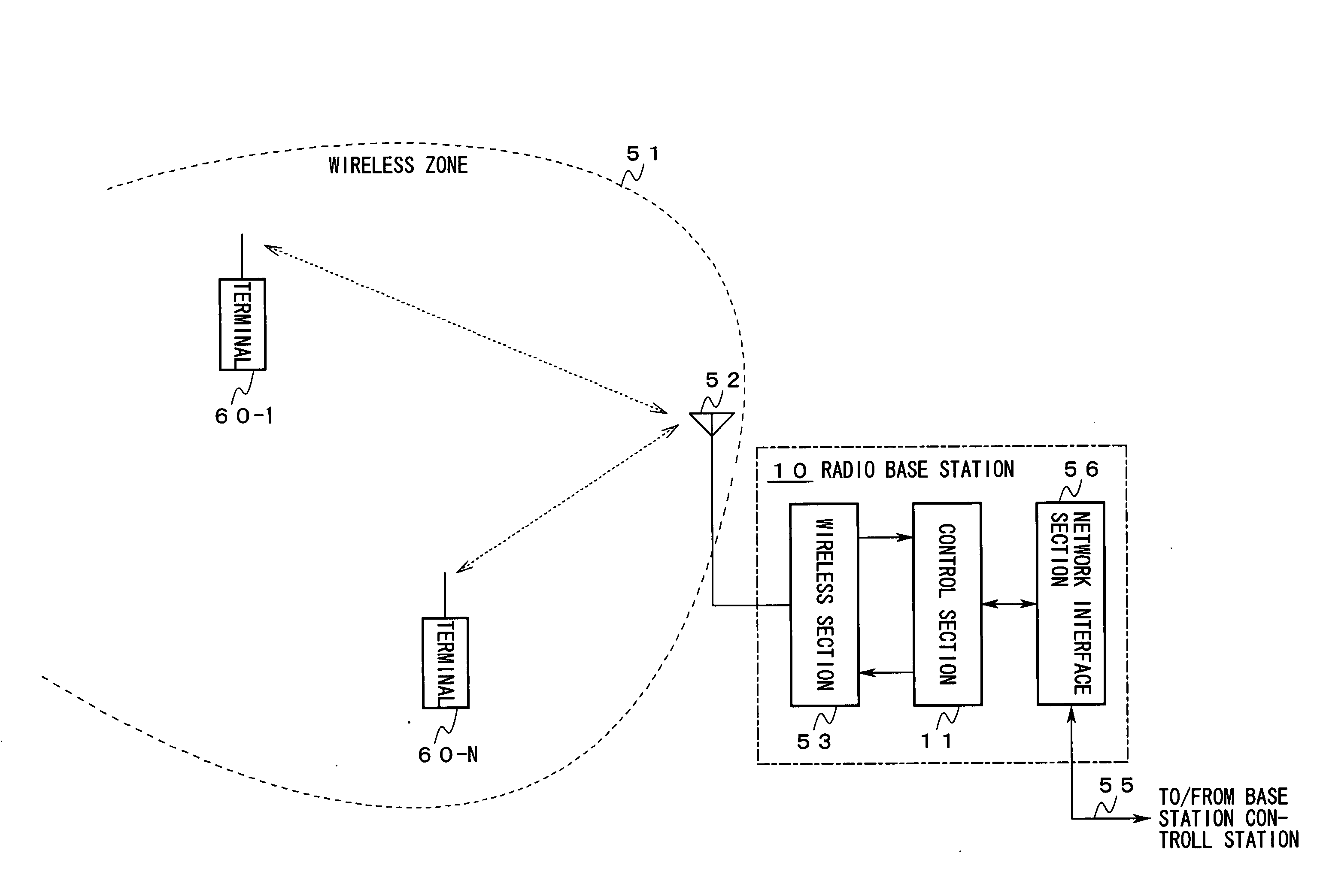
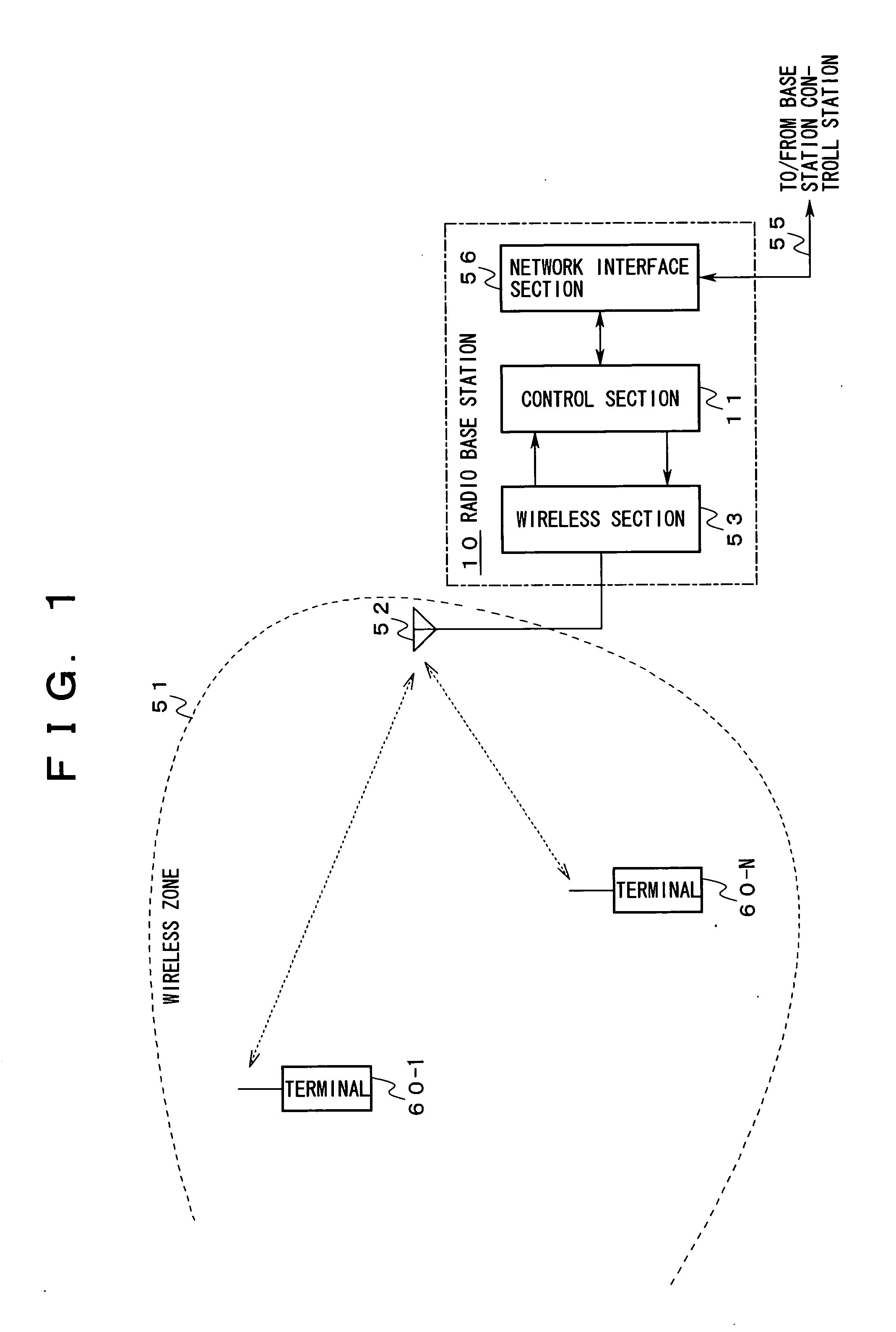
[0114]FIG. 1 is a view showing first to fourth embodiments of the present invention.

[0115] In this embodiment, a radio base station 10 is arranged instead of the radio base station 50, and a control section 11 is arranged instead of the control section 54 in this radio base station 10.

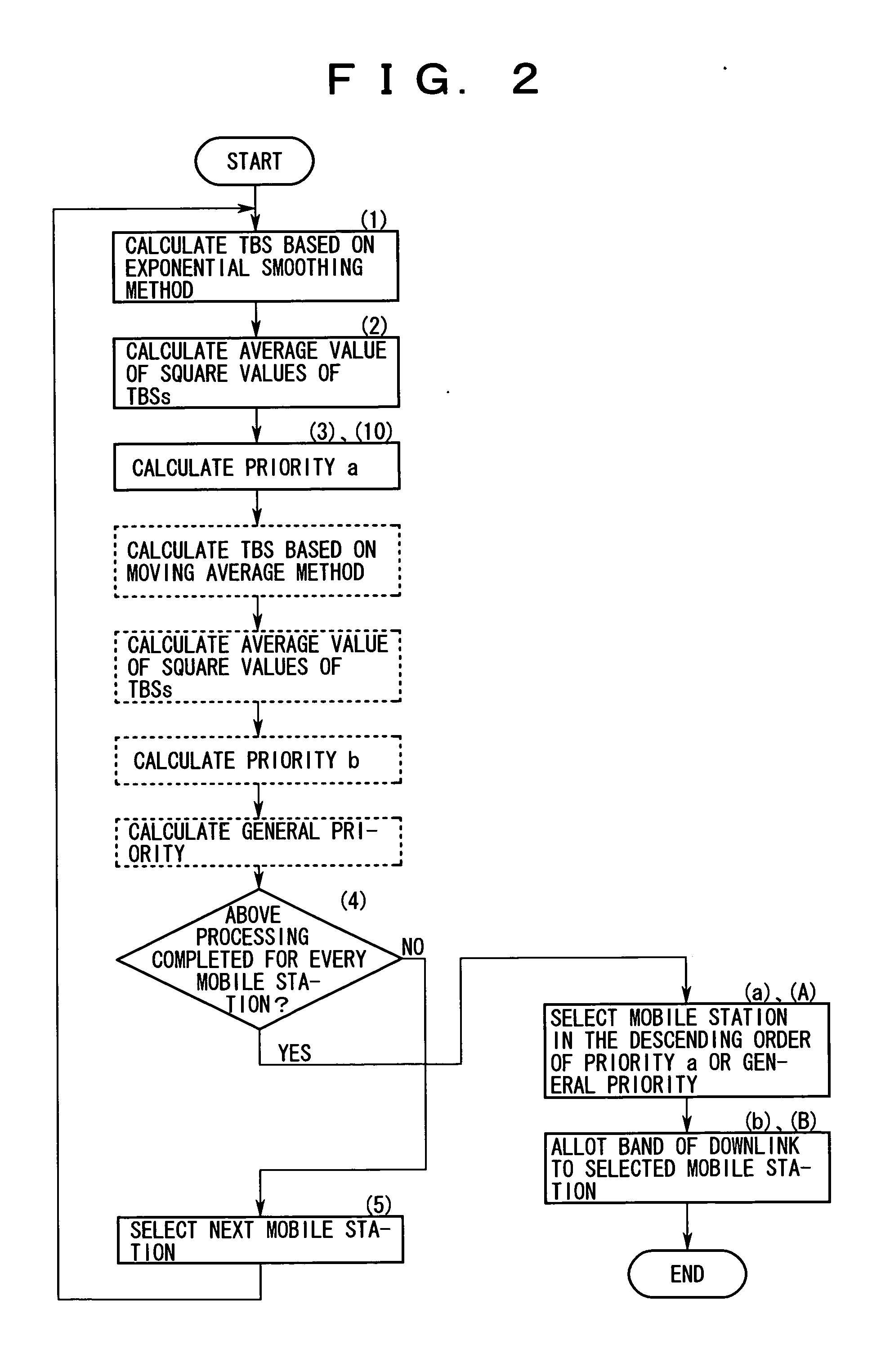
[0116] The operation of a transmission-band allotting apparatus in a first embodiment of the present invention will next be explained with reference to FIGS. 1 and 2.

[0117] The features of this embodiment are characterized in the procedure of processing of the following scheduling performed by the control section 11 arranged in the radio base station 10.

[0118] In the following description, a code 60-n is noted additionally to a mobile station shown by an identifier n of the mobile station.

[0119] The control section 11 sequentially makes the following arithmetic calculation for the mobile station 60-n shown by the identifier n pertinent to each of 1 to N.

[0120] With respect to a time series m, a f...

second embodiment

[0127] The operation of a transmission-band allotting apparatus in a second embodiment of the present invention will next be explained with reference to FIGS. 1 and 2.

[0128] This embodiment is characterized in the procedure of processing of the following scheduling performed by the control section 111 arranged in the radio base station 10.

[0129] The control section 11 performs the following processing to all the mobile stations 60-1 to 60-N (for brevity, it is here supposed that the mobile stations 60-1 to 60-N wait for the allotment of the band of the downlink based on HSDPA in parallel with each other) in addition to the arithmetic calculation for calculating the above-described priority a.

[0130] With respect to the time series m and rn(m) as TBS of the mobile station 60-n acquired in the process of scheduling, an average value R(m) of its rn(m) relating to all the mobile stations 60-1 to 60-N and an average value S(m) of these square values of rn(m) are calculated by repeating...

third embodiment

[0139] The operation of a transmission-band allotting apparatus in a third embodiment of the present invention will next be explained with reference to FIGS. 1 and 2.

[0140] This embodiment is characterized in the procedure of the following processing performed by the control section 11 arranged in the radio base station 10.

[0141] The control section 11 performs processing different from that of each of the above-described first and second embodiments with respect to the following points.

[0142] No arithmetic calculation ((2) and (7) of FIG. 2) based on the above-described recurrence formulas (4), (7) is made.

[0143] Instead of the arithmetic calculation based on the above-described formulas (5), (8), the priority a (=Pan(m)) and the priority b (=Pbn(m)) are calculated by making the arithmetic calculation shown in the following formulas (11), (12) ((10 and (11) of FIG. 2).

Pan(m)=rn(m) / Rn(m)  (11)

Pbn(m)=rn(m) / R(m)  (12)

[0144] Further, the control section 11 calculates the general...


PUM


Abstract

The present invention relates to a transmission-band allotting apparatus for suitably allotting a band used for transmitting a packet to each terminal in a packet radio transmission system. An object of the present invention is to provide a fair service to individual terminals, and to improve the throughput of downlink. Therefore, the transmission-band allotting apparatus according to the present invention is constructed by preferentially allotting the band of the downlink to terminals in a descending order of ratios of a deviation from an average value of transmission qualities notified by the terminal and a dispersion of each of the transmission qualities.

Description

CROSS REFERENCE TO RELATED APPLICATION [0001] This application is a continuation application of International Application PCT / JP 03 / 05538, filed Apr. 30, 2003, and designating the U.S.[0002] 1. Field of the Invention [0003] The present invention relates to a transmission-band allotting apparatus which suitably allots to individual terminals a band used for transmitting packets in a radio transmission system in which transmission information is transmitted in the unit of a packet. [0004] 2. Description of the Related Art [0005] In a wide-band CDMA (Code Division Multiple Access) mobile communication system, it is possible to provide a packet transmission service at a speed of several hundred kilobits / second. [0006] However, in such a mobile communication system, for example, HSDPA (High Speed Downlink Packet Access) is being applied and practically used as a technique able to greatly raise a down transmission speed without increasing an occupied band in a wireless frequency band so a...

Claims


Application Information

Patent Timeline
Patent Type & Authority Applications(United States)
IPC IPC(8): H04J3/00H04L1/00H04L1/20H04L47/76H04W16/02H04W72/54H04W84/12
CPCH04W24/10H04W72/085H04W72/0453H04W72/542
Inventor KIMURA, DAI
Owner FUJITSU LTD
Learn More