Multi-user telephone system

a multi-user, telephone system technology, applied in the field of telephone communications, can solve the problems of large number of cable pairs that are required for conventional telephone voice transmission, high cost of private branch exchange that is included in a shared multi-exchange system, and high cost of user telephone installation

Inactive Publication Date: 2005-10-13
ATRIS
View PDF13 Cites 10 Cited by
  • Summary
  • Abstract
  • Description
  • Claims
  • Application Information

AI Technical Summary

Problems solved by technology

Another is the high cost of the private branch exchange that is included in a shared multi-exchange system.
A shortcoming common to both prior art arrangements is the large number of cable pairs that is required for conventional telephone voice transmissi

Method used


Image

  • Multi-user telephone system
  • Multi-user telephone system
  • Multi-user telephone system

Examples


Embodiment Construction

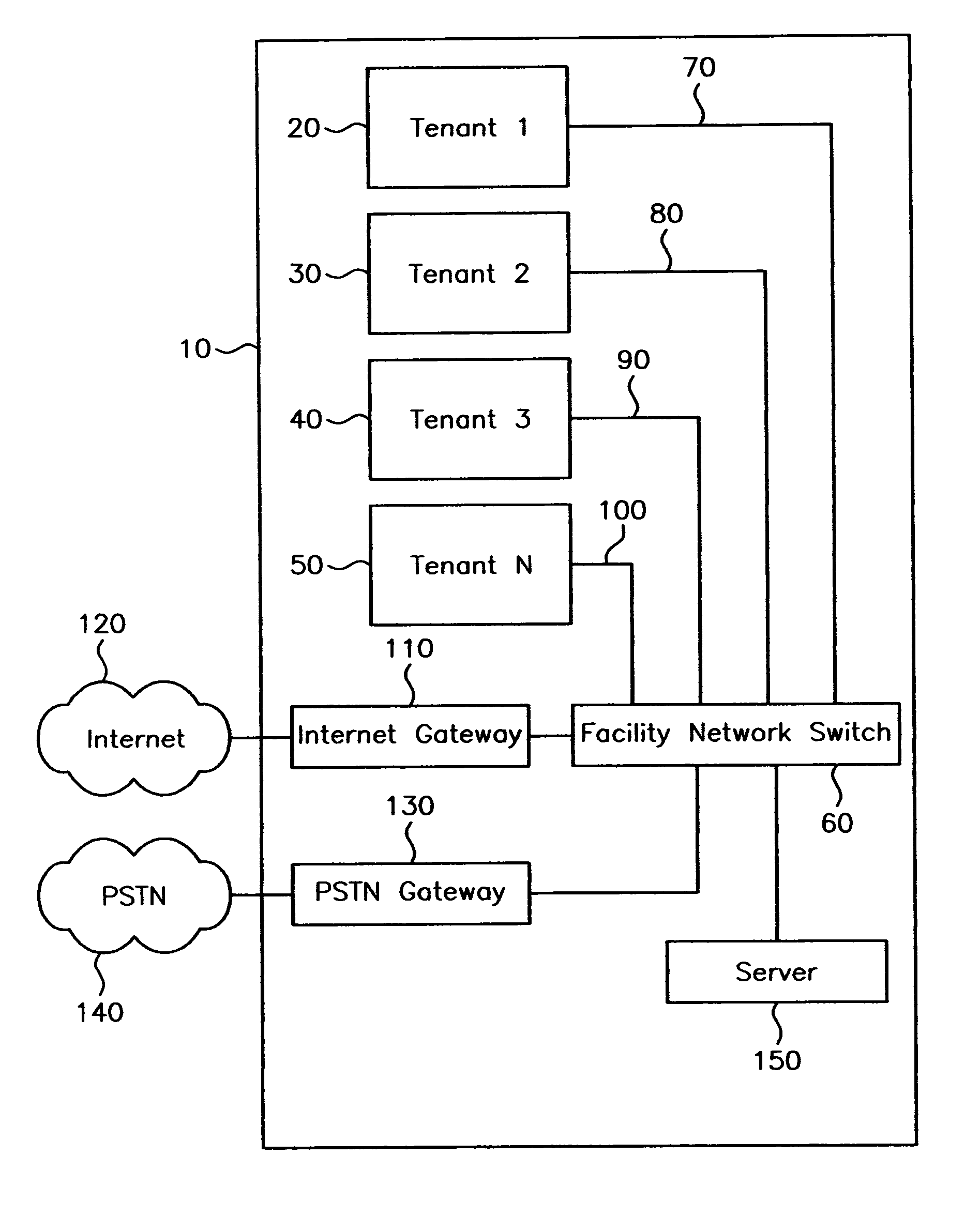
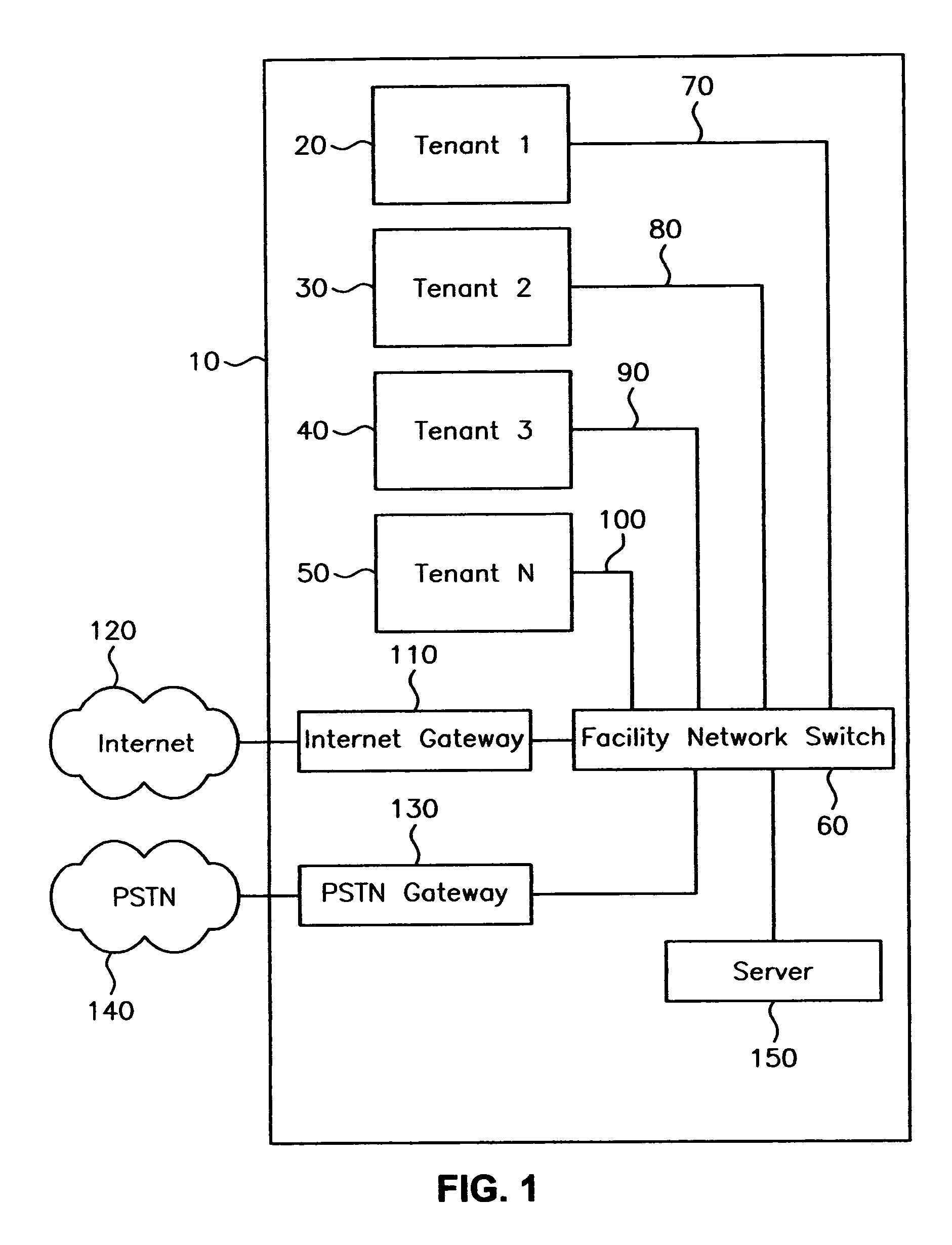
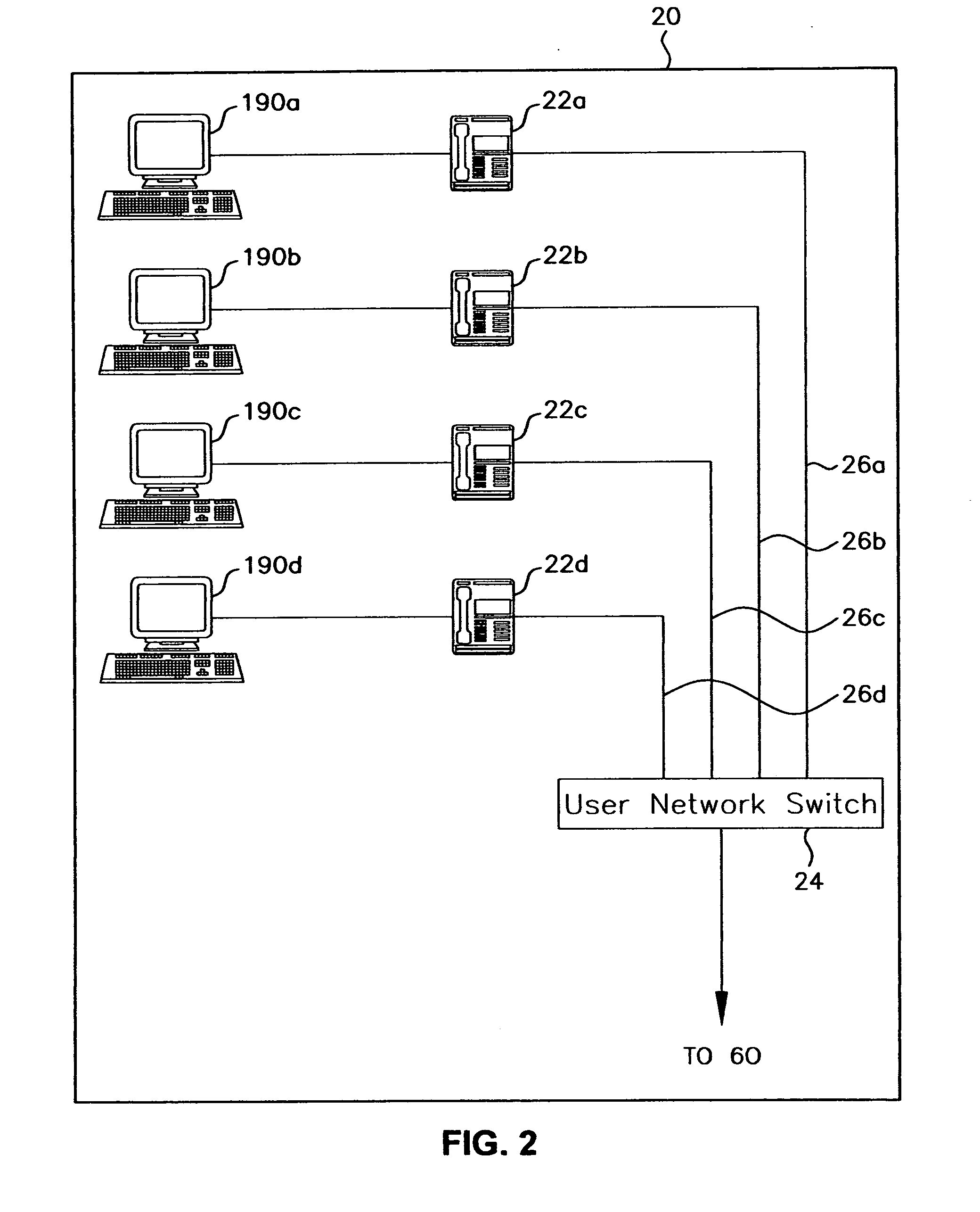
[0008] Referring to FIGS. 1 and 2, a multi-user telephone system 10, constructed in accordance with the present invention, includes a first user telephone network 20, also identified in FIG. 1 as Tenant 1, and a second user telephone network 30, also identified in FIG. 1 as Tenant 2. User telephone networks 20 and 30 are in the same general location, such as an office building. As shown in FIG. 1, a multi-user telephone system, constructed in accordance with the present invention, can have more than two user telephone networks. The multi-user telephone system shown in FIG. 1 has two additional user telephone networks 40 and 50, also identified in FIG. 1 as Tenant 3 and Tenant 4, respectively.

[0009] As shown in FIG. 2, each user telephone network includes a plurality of VOIP telephone extensions, identified by reference numerals 22a, 22b, 22c, and 22d. A VOIP telephone extension is one that can develop voice over internet protocol (VOIP) signals. A Polycom IP 500 telephone extension...


PUM


Abstract

A multi-user telephone system composed of a plurality of user networks installed at the same general location. Each user network has a different telephone number and a plurality of VOIP extensions each having a different extension number. A server, upon confirming the address of an outgoing VOIP signal as an address of an intended recipient of the outgoing VOIP signal, permits the outgoing VOIP to be conducted to the internet. The VOIP extensions also can develop outgoing PSTN signals for transmission via a public switched telephone network. The server, upon detecting a PSTN outgoing signal, permits the outgoing PSTN signal to be conducted to a public switched telephone network. The server also confirms that the address of an incoming signal, from the internet or from a public switched telephone network, is an address of an extension in one of the user networks.

Description

FIELD OF THE INVENTION [0001] The present invention relates, in general, to telephone communications and, in particular, to a multi-user telephone system composed of a plurality of user networks installed at the same general location with each network having a different telephone number and a plurality of extensions. BACKGROUND OF THE INVENTION [0002] Telephone system installations in multi-occupant facilities, where each occupant of the facility has a different telephone number and a plurality of extensions, in the past have been arranged either: (a) as separate user systems set up by the occupants individually and separately connected to a public switched telephone network (PSTN) through a local telephone switch or router each dedicated to the individual user telephone system, or (b) as multi-exchange shared systems set up by, for example, the landlords of the facilities, with each individual user telephone exchange system in the overall shared system connected to a public switche...

Claims


Application Information

Patent Timeline
IPC IPC(8): H04L12/66H04L29/12H04M3/533H04M7/00
CPCH04L29/12018H04L61/10H04M1/2535H04M7/006H04M3/533H04M7/0057H04M1/733
Inventor BERKOWITZ, JUDAH S.SAGER, EDWARD J.
Owner ATRIS
Why Eureka
Try Eureka