Direction indicating device and direction indicating method

a direction indication and direction technology, applied in the direction of digital data authentication, instruments, image analysis, etc., can solve the problems of insufficient space for enlarge the finger plate, the mobile information terminal cannot be downsized or thinned, and the inability to carry out direction indication easily and reliably

Inactive Publication Date: 2005-10-13
MURATA MASCH LTD
View PDF3 Cites 13 Cited by
  • Summary
  • Abstract
  • Description
  • Claims
  • Application Information

AI Technical Summary

Benefits of technology

[0008] According to an aspect of the present invention, a direction indicating device includes a fingerprint input unit, a fingerprint registration unit, a fingerprint authentication unit and a control unit. The fingerprint input unit inputs a fingerprint of a finger by being touched with the finger. The fingerprint registration unit registers a fingerprint previously as a standard fingerprint. The fingerprint authentication unit detects a matching part of the input fingerprint input from the fingerprint input unit and the standard fingerprint registered previously in the fingerprint registration unit by being associated with the input fingerprint by comparing the input fingerprint and the standard fingerprint. The control unit determines an indicating direction in accordance with a detection result of the fingerprint authentication unit.
[0009] The direction indicating device determines the indicating direction by using a fingerprint authentication function. That is, the fingerprint authentication unit detects a matching part of the input fingerprint and the standard fingerprint associated with the input fingerprint by comparing the input fingerprint and the standard fingerprint, and determines the indicating direction in accordance with the detection result of the fingerprint authentication unit.
[0010] According to another aspect of the present invention, in the direction indicating device, the control unit determines the indicating direction in accordance with a detection result of a presence or absence detecting process and a matching part detecting process. In the presence or absence detecting process, a detection is carried out for whether or not the input fingerprint is the standard fingerprint registered in the fingerprint registration unit. In other words, a detection is carried out for whether or not the input fingerprint exists in the standard fingerprint registered in the fingerprint registration unit. In the matching part detecting process, by using a general fingerprint authentication function that verifies the input fingerprint with the standard fingerprint, in the verification of the input fingerprint and the standard fingerprint that is carried out at a fingerprint authentication, a detection is carried out for which part of the input fingerprint and the standard fingerprint match with one another. Accordingly, it becomes unnecessary to move the finger while touching a finger authentication sensor (a finger plate or a key) as in a conventional art. As a result, the direction indication can be carried out easily and reliably while being space-saving.
[0011] According to another aspect of the present invention, for determining the indicating direction in accordance with the detection result of the matching part of the input fingerprint and the standard fingerprint, the control unit is preferable to detect a changing direction of the matching part of the input fingerprint and the standard fingerprint and to make the changing direction as the indicating direction of the finger.
[0012] According to another aspect of the present invention, in case the matching part of the input fingerprint and the standard fingerprint is located at a center part of both of the fingerprints, the control unit is preferable to determine a presence or an absence of a click input in accordance with an increase or a decrease in an area of the matching part.
[0013] According to another aspect of the present invention, the direction indicating device further includes a display unit which can display a pointer (cursor). The control unit is preferable to control the moving direction of the pointer according to the determined indicating direction.

Problems solved by technology

However, the mobile information terminal such as a mobile telephone has a limited space and does not have a sufficient space to enlarge the finger plate.
If a large finger plate is provided, the mobile information terminal cannot be downsized or thinned.
Such a drawback also exists in a device in which a camera unit and a LED are provided in an inner space of the key.

Method used


Image

  • Direction indicating device and direction indicating method
  • Direction indicating device and direction indicating method
  • Direction indicating device and direction indicating method

Examples


Embodiment Construction

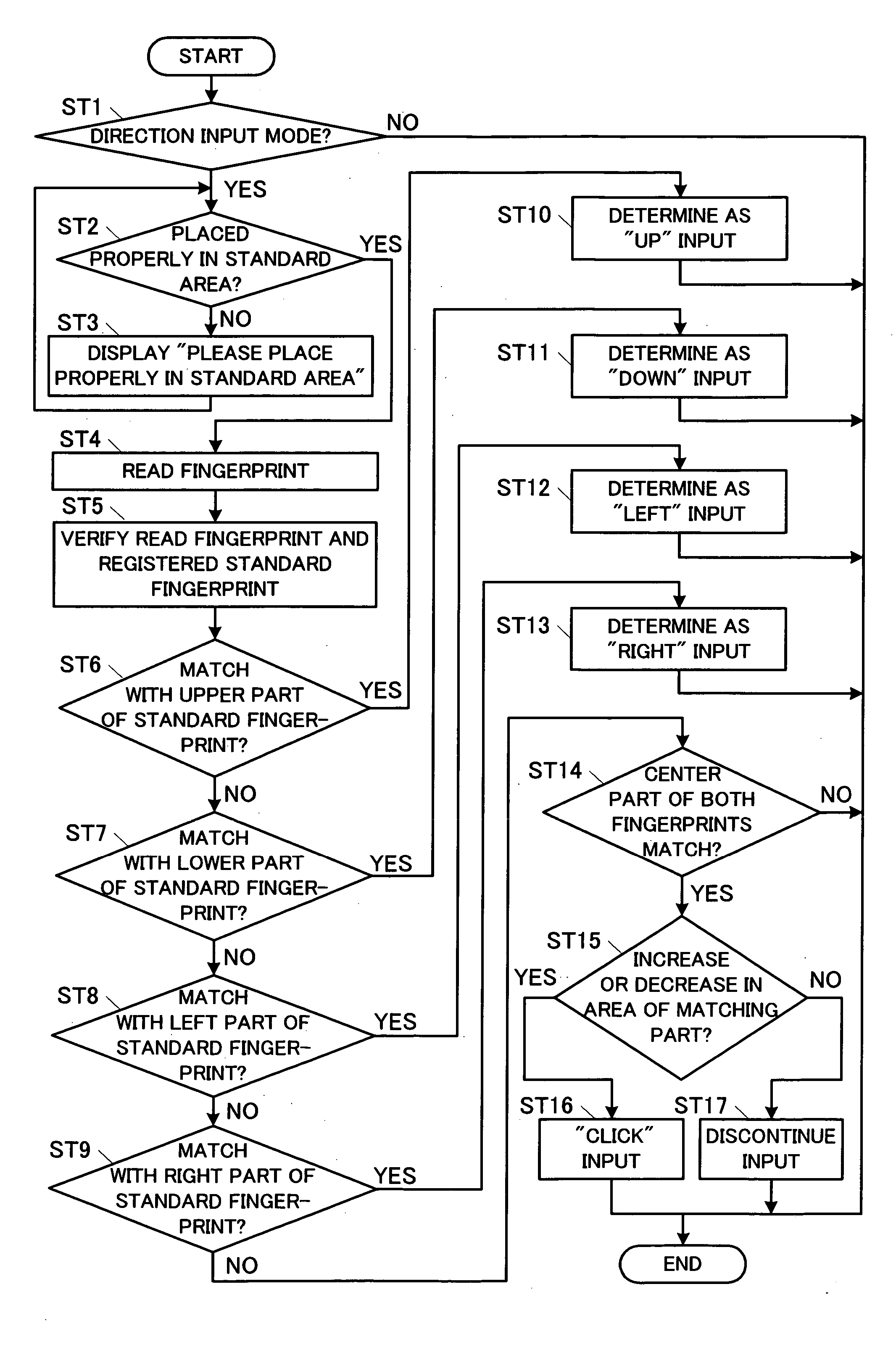
[0018] An embodiment of the present invention will be described.

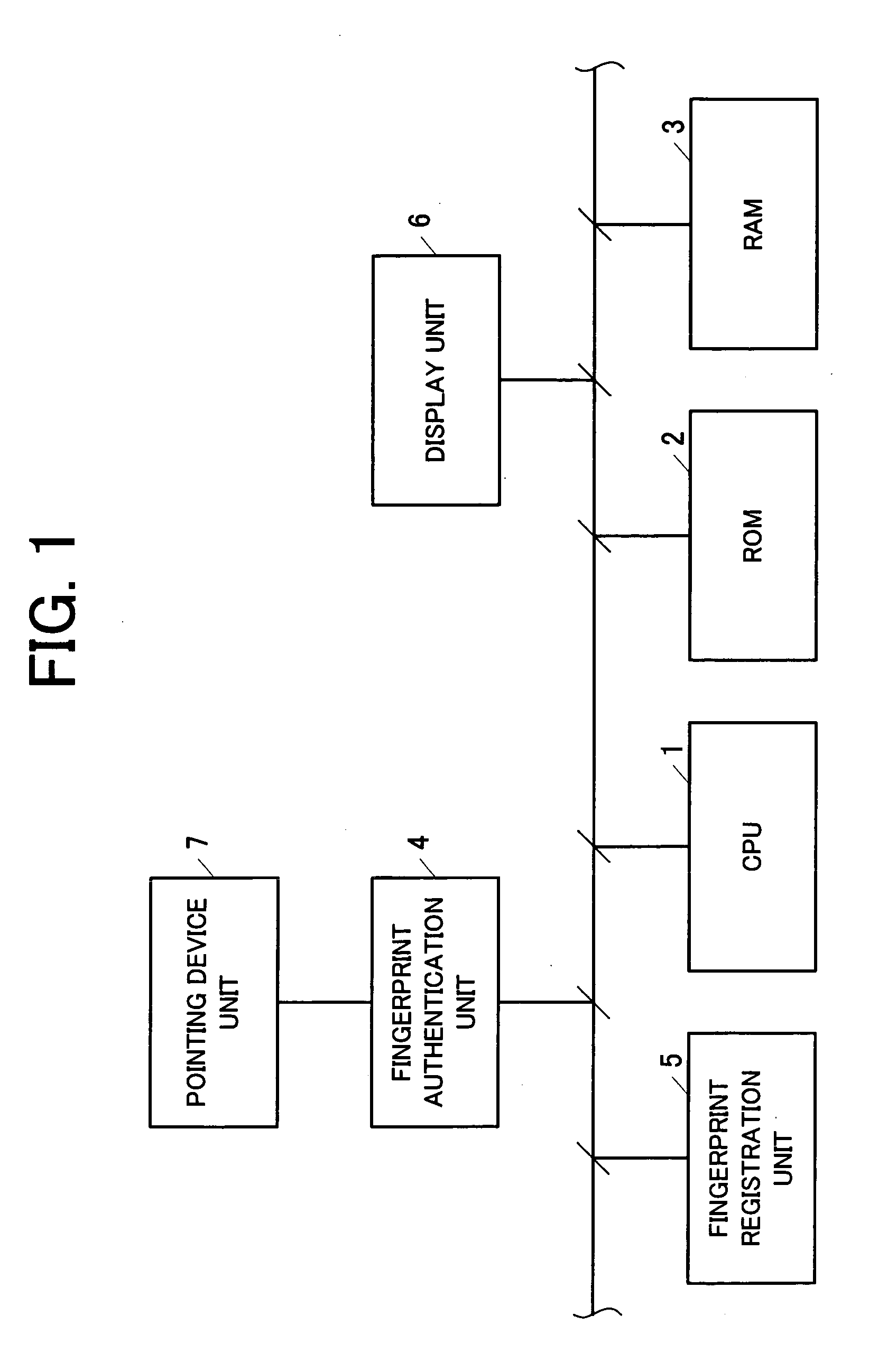
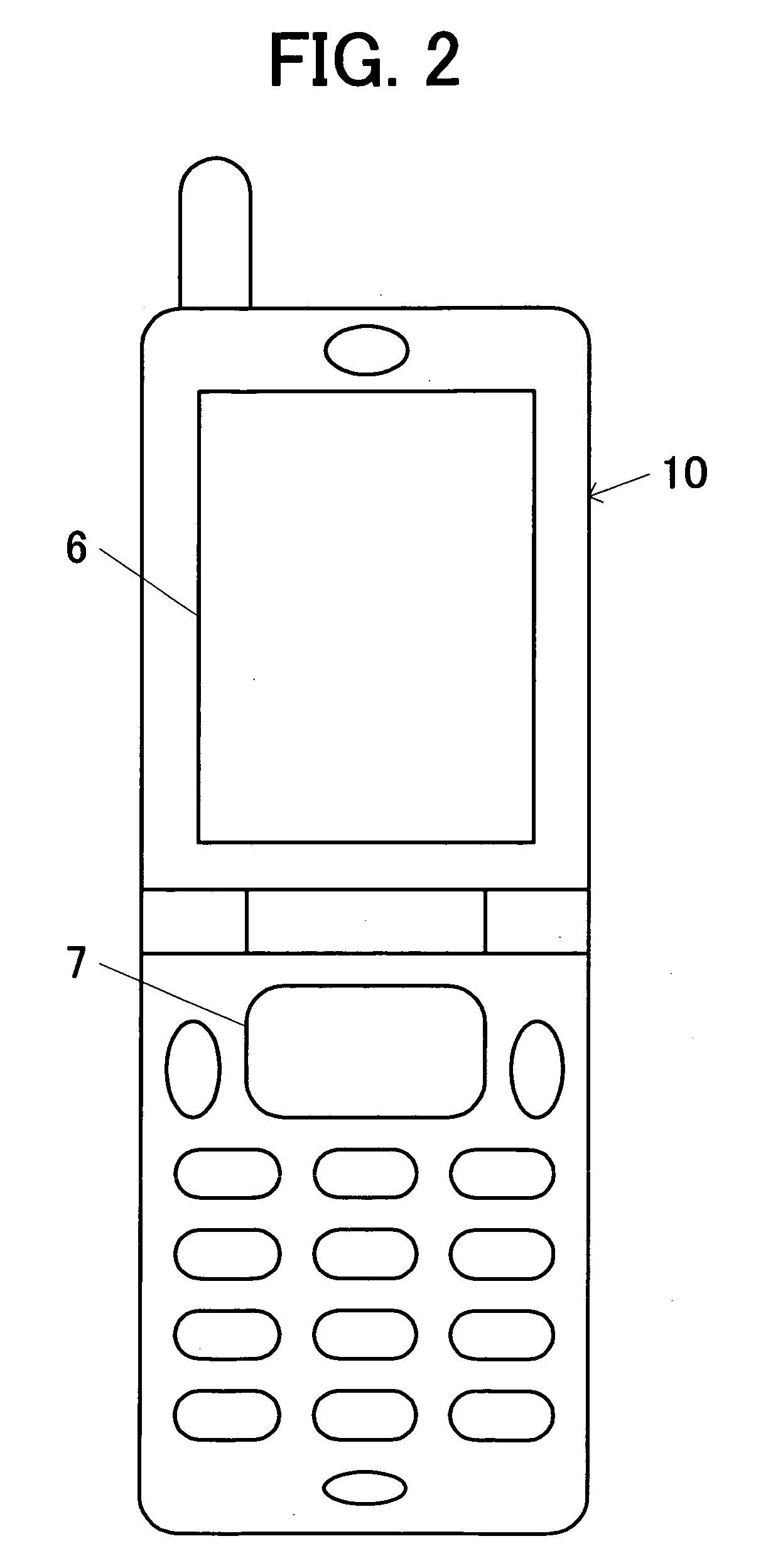
[0019]FIG. 1 is a block diagram showing an example of a configuration of a mobile information terminal having a direction indicating device according to an embodiment of the present invention. The mobile information terminal includes a Central Processing Unit (CPU) (a control unit) 1, a Read Only Memory (ROM) 2, a Random Access Memory (RAM) 3, a fingerprint authentication unit 4, a fingerprint registration unit 5, a display unit 6 and a pointing device unit (a fingerprint input unit) 7.

[0020] The control unit 1 integrally controls each component of the mobile information terminal in accordance with a program stored in the ROM 2. The control unit 1 has a function for determining an indicating direction in accordance with a detection result of the fingerprint authentication unit 4.

[0021] The ROM 2 stores a program or the like for controlling an operation of the entire mobile information terminal. The RAM 3 stores, for ...


PUM


Abstract

A direction indicating device includes a fingerprint input unit, a fingerprint registration unit, a fingerprint authentication unit and a control unit. The fingerprint input unit inputs a fingerprint of a finger by being touched with the finger. The fingerprint registration unit registers a fingerprint previously as a standard fingerprint. The fingerprint authentication unit detects a matching part of the input fingerprint input from the fingerprint input unit and the standard fingerprint registered previously in the fingerprint registration unit by being associated with the input fingerprint by comparing the input fingerprint and the standard fingerprint. The control unit determines an indicating direction in accordance with a detection result of the fingerprint authentication unit.

Description

BACKGROUND OF THE INVENTION [0001] 1. Field of the Invention [0002] The present invention relates to a direction indicating device and a direction indicating method for indicating a moving direction of a pointer or the like by using a fingerprint authentication. [0003] 2. Description of Related Art [0004] In a mobile information terminal such as a mobile telephone, as a pointing device for moving a pointer (cursor) on a display screen, for example, a pointing device is disposed on an outer case of the mobile information terminal. The pointing device includes a finger plate, an image pickup device, a light condenser lens and a light emitting device. The pointing device takes an image of a pattern (for example, a fingerprint of a fingertip) placed on a surface of the finger plate by the image pickup device. While touching the surface of the finger plate with the fingertip, when the fingertip is moved, an image taken by the image pickup device changes accompanying the movement of the f...

Claims


Application Information

Patent Timeline
Patent Type & Authority Applications(United States)
IPC IPC(8): G06F3/033G06F3/00G06F3/0354G06F21/00G06K9/00G06T7/00
CPCG06F3/03547G06F21/32G06F3/038
Inventor TANAKA, HIDEKI
Owner MURATA MASCH LTD
Why Eureka
Try Eureka