Screw compressor

Active Publication Date: 2005-10-13
BITZER KUEHLMASCHINENBAU GMBH
View PDF12 Cites 29 Cited by
  • Summary
  • Abstract
  • Description
  • Claims
  • Application Information

AI Technical Summary

Benefits of technology

[0008] The provision of the injection opening, via which the refrigerant is injected into the inlet passage section in the compressor housing, means that it is possible to prevent the propagation of pressure oscillations or pulsations beyond the first inlet passage section and thereby to avoid the production of noise in the conduit system of the refrigerant injection, since reducing the cross section of the injection opening prevents unattenuated propagation of pressure oscillations or pulsations beyond the first inlet passage section.
[0036] In this context, it is expediently provided that the inlet in the control slide is connected to the injection opening via a section, which is of variable length, of the first inlet passage section, so that the control slide can be adjusted in a simple way.

Problems solved by technology

With screw compressors of this type, the problem arises that on account of the fact that the compression spaces surrounded by the screw rotors and screw rotor bores move past the inlet, pressure oscillations or pulsations occur, propagate through the conduit system of the refrigerant injection and lead to noise, and in the most serious case even to damage or sealing problems.

Method used


Image

  • Screw compressor
  • Screw compressor
  • Screw compressor

Examples


Embodiment Construction

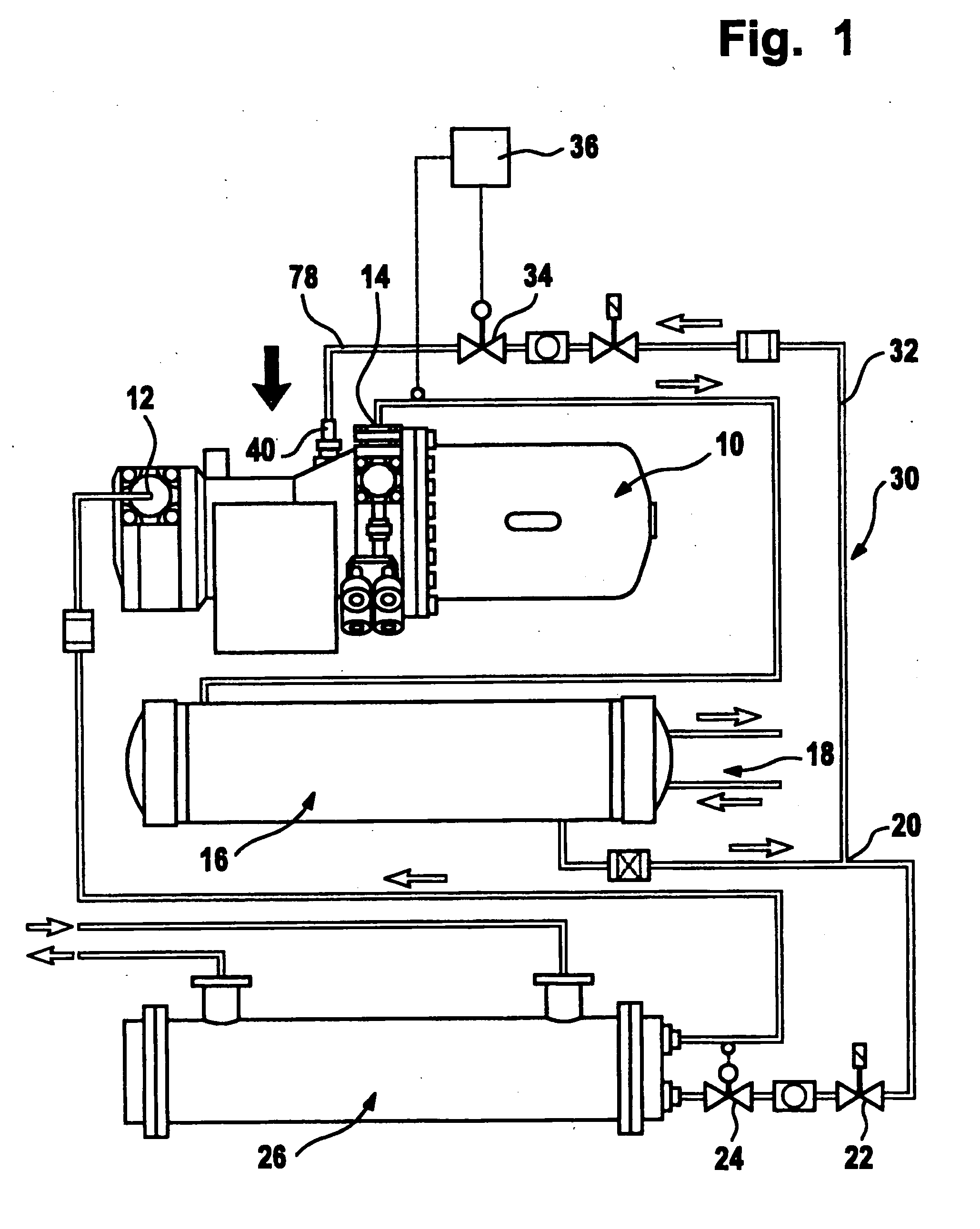
[0044] A first exemplary embodiment of a screw compressor according to the invention, illustrated in FIG. 1, comprises a compressor housing, which is denoted overall by reference number 10 and on which a suction connection 12 and a pressure connection 14 are provided, refrigerant being sucked in at the suction connection 12 and compressed refrigerant being delivered at the pressure connection 14.

[0045] The compressed refrigerant delivered at the pressure connection 14 is first of all fed to a liquefier 16 in a cooling circuit 18, and from the liquefier 16 passes as liquid refrigerant to a branching point 20, from which the cooling circuit 18 leads onward to a solenoid valve 22 and to a downstream expansion valve 24 and then to an evaporator 26, from which the refrigerant that has been evaporated in the evaporator 26 is then conducted back to the suction connection.

[0046] In addition to the cooling circuit 20, a refrigerant injection 30 is provided, which branches off from the cool...


PUM


Abstract

Disclosed is a screw compactor comprising two screw rotors which are disposed in screw rotor bores inside a compressor housing and compress a coolant that enters at a coolant inlet and discharge said coolant at a coolant outlet, and a coolant inlet that is arranged within the compressor housing, said coolant being supplied by a coolant-injecting device via a conduit system in order to additionally cool the screw compressor. The inlet is disposed so as to extend into compression spaces that are enclosed by the screw rotors and the screw rotor bores. The aim of the invention is to create a screw compactor in which the compressive oscillations occurring at the inlet do not travel at all or only in an attenuated manner into the conduit system for the coolant-injecting device. Said aim is achieved by mounting a first inlet duct section which runs inside the compressor housing upstream of the inlet, an injection port for the coolant that is supplied by the coolant-injecting device extending into said first inlet duct section, while making a cross-sectional area of the injection port more than about four times smaller than a cross-sectional area of the first inlet duct section.

Description

[0001] This application is a continuation of international application number PCT / EP2003 / 013224 filed on Nov. 25, 2003. [0002] The present disclosure relates to the subject matter disclosed in international application number PCT / EP2003 / 013224 of Nov. 25, 2003 and German applications number 102 58 136.3 of Dec. 3, 2002 and number 102 58 145.2 of Dec. 4, 2002, which are incorporated herein by reference in their entirety and for all purposes.BACKGROUND OF THE INVENTION [0003] The invention relates to a screw compressor, comprising two screw rotors, which are disposed in screw rotor bores in a compressor housing, compress a refrigerant that enters at a refrigerant inlet and allow the refrigerant to leave at a refrigerant outlet, and an inlet, which is provided in the compressor housing, for refrigerant, which is supplied by a refrigerant injection via a conduit system, for additional cooling of the screw compressor, the inlet being disposed in such a manner that it opens out in compres...

Claims


Application Information

Patent Timeline
Patent Type & Authority Applications(United States)
IPC IPC(8): F04C18/16F04C28/12F04C29/00
CPCF04C18/16F04C29/0014F04C28/12
Inventor HOSSNER, KLAUS
Owner BITZER KUEHLMASCHINENBAU GMBH
Why Eureka
Try Eureka