Screw device for orthodontic treatment

a screw and orthodontic technology, applied in the field of screw devices for orthodontic treatment, can solve the problems of prone to loosening of fixtures, springs are prone to impinge on gingivals, and do not provide the function of spring hooking

Inactive Publication Date: 2005-10-13
LIN CHENG YI
View PDF5 Cites 25 Cited by
  • Summary
  • Abstract
  • Description
  • Claims
  • Application Information

AI Technical Summary

Benefits of technology

[0010] The main objective of the invention is to provide an improvement for a screw device for orthodontic treatment. The screw device in accordance with the present invention compris...

Problems solved by technology

However, the abutment of U.S. Pat. No. 4,988,292 does not provide the function of spring hooking.
Even if someone tries to hook the spring on the abutment, the spring will be prone to impinge the gingival as previously illustrated.
In addition, the fixture is prone to loose since it has identical outer threads and identical outer diameter throughout the entire fixture.
None part of the occlusal screw nor anchoring screw is exposed outside the implant, such that they cannot be used for spring hooking.
Even if the spring can be tied (not hook) on a bracket of U.S. Pat. No. 5,836,768, the spring will be p...

Method used


Image

  • Screw device for orthodontic treatment
  • Screw device for orthodontic treatment
  • Screw device for orthodontic treatment

Examples


Embodiment Construction

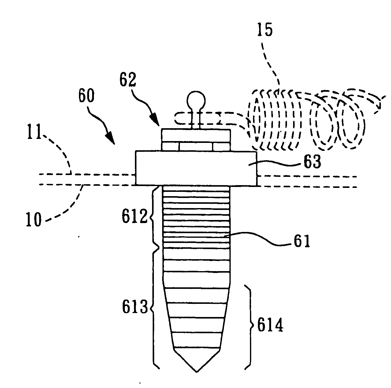
[0037] The elements described thereinafter, such as: maxilla (or mandible) 10, gingiva 11, tooth 12, orthodontic archwire 13, orthodontic bracket 14, and spring 15 (or rubber band) for orthodontic treatment etc., and their relative position arranged in the mouth are all similar to the prior arts shown in FIG. 1 and they are not the technical characteristics of the invention, so they will be given same element names and referential numbers and their detailed composition, arrangement position, and function are not described herein repetitiously. One thing is worth mentioning: although the embodiment of the prior arts shown in FIG. 1 only depicts an embodiment that a correction device is arranged on the outside of the upper jaw, however, it may also be arranged on the outside or inside surface of maxilla (or mandible).

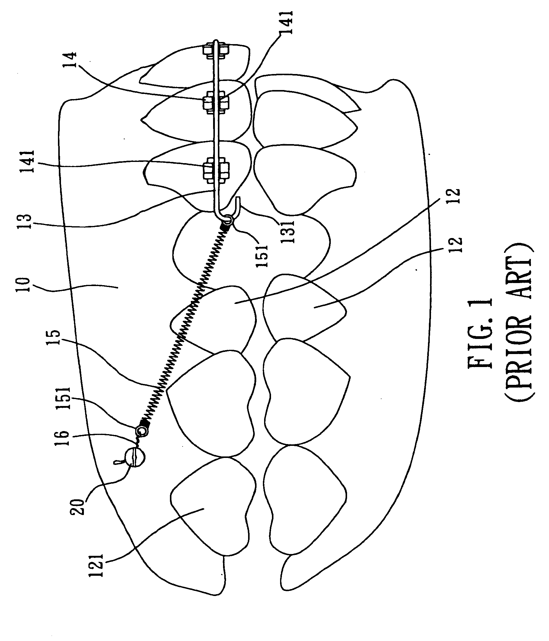
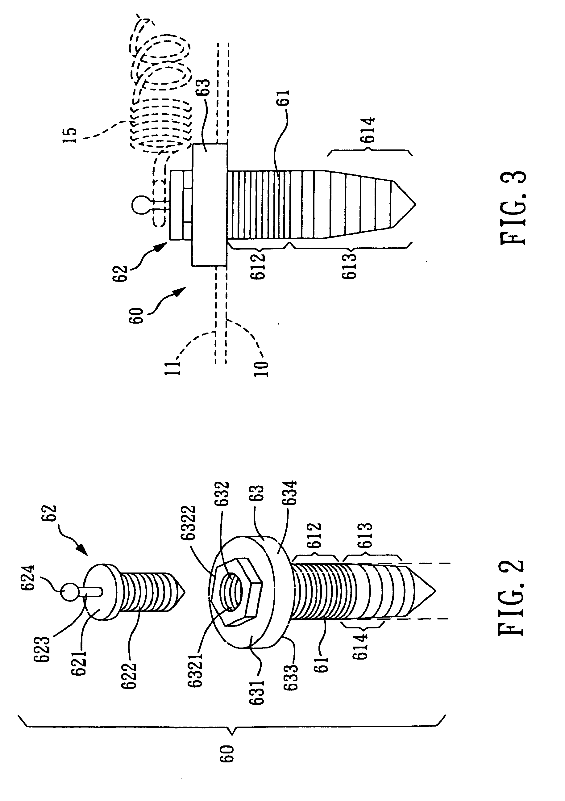
[0038] Please refer to FIG. 2 and FIG. 3. FIG. 2 is the first preferred embodiment for the screw device according to the invention for orthodontic treatment. FIG. 3 is a...


PUM


Abstract

A screw device for orthodontic treatment comprises a screw-body part, a platform part integrally formed with the screw-body part, and a head part. The head part is detachable from and exposed outside the screw-body part and is operatable to hook a spring (or rubber band) for orthodontic treatment. Since the head part is detachable, various types of head parts can be chosen to attach on the same platform part and screw-body part for performing different orthodontic treatments. Cost to manufacture the screw device is lower, and flexibility and convenience to use the screw device are higher. The screw device further comprises a detachable auxiliary unit which can be firmly clamped between the head part and platform part. The auxiliary unit has a hollow ring portion having a center hole, a first accessory member and a second accessory member. The size of the center hole is smaller than a flat cap of head part, such that it can be clamped between the head part and platform part.

Description

FIELD OF THE INVENTION [0001] The invention relates to a screw device for orthodontic treatment, especially to a screw device that may be arranged in the maxilla (or mandible) and is capable of positioning the spring used for orthodontic treatment and accommodating the orthodontic archwire. This application is a continue-in-part (CIP) application of pending U.S. patent application Ser. No. 10 / 885,580 filing date Jul. 8, 2004, which is yet a continue-in-part (CIP) application of pending U.S. patent application Ser. No. 10 / 732,292 filing date Dec. 11, 2003, which is yet a continue-in-part (CIP) application of U.S. patent application Ser. No. 10 / 359,577 filing date Feb. 7, 2003 which is now granted as U.S. Pat. No. 6,722,879, which is yet a continue-in-part (CIP) application of U.S. patent application Ser. No. 10 / 211,037 filing date Aug. 5, 2002 which is now granted as U.S. Pat. No. 6,726,475. BACKGROUND OF THE INVENTION [0002] As shown in FIG. 1, in a conventional orthodontic treatmen...

Claims


Application Information

Patent Timeline
IPC IPC(8): A61C3/00A61C7/00A61C8/00
CPCA61C7/00A61C8/0096A61C8/0022
Inventor LIN, CHENG-YI
Owner LIN CHENG YI
Why Eureka
Try Eureka