
Push-up trainer

a trainer and push-up technology, applied in the field of push-up trainers, can solve the problems of user injury, complex structure of push-up trainers,

Inactive Publication Date: 2005-10-13
WEN WEI TZU
View PDF4 Cites 19 Cited by
  • Summary
  • Abstract
  • Description
  • Claims
  • Application Information

AI Technical Summary

Benefits of technology

[0007] The primary objective of the present invention is to provide a push-up trainer, which is structurally preferably simple and safe.
[0008] The secondary objective of the present invention is to provide a push-up trainer, which is adjustable in accordance with arm length of different users to reduce operational inconvenience.

Problems solved by technology

However, the conventional push-up trainer 80 is structurally complex, having numerous component parts, and the user is subject to injury incurred by the collapsible guiding member 84.

Method used


Image

  • Push-up trainer
  • Push-up trainer
  • Push-up trainer

Examples


Embodiment Construction

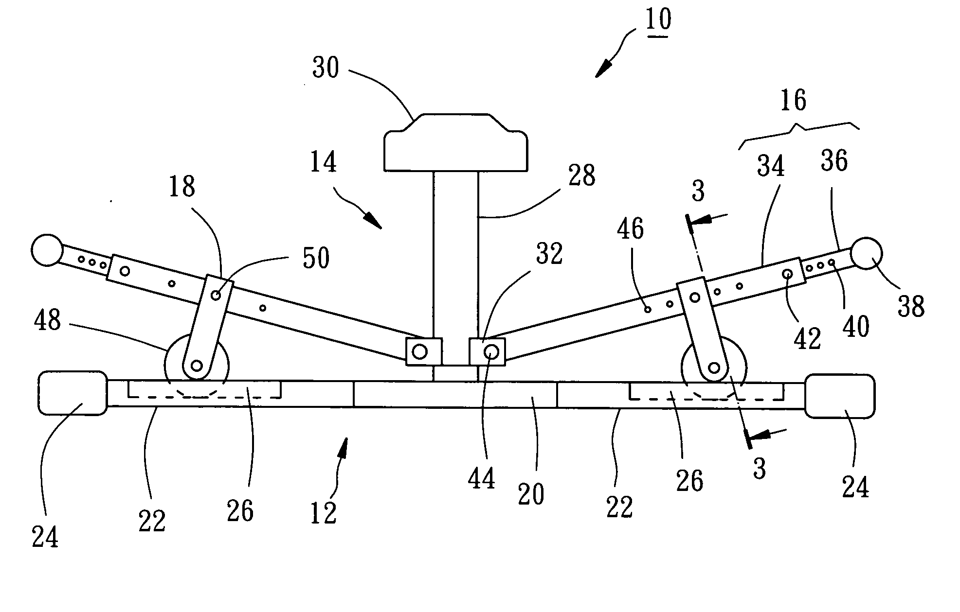
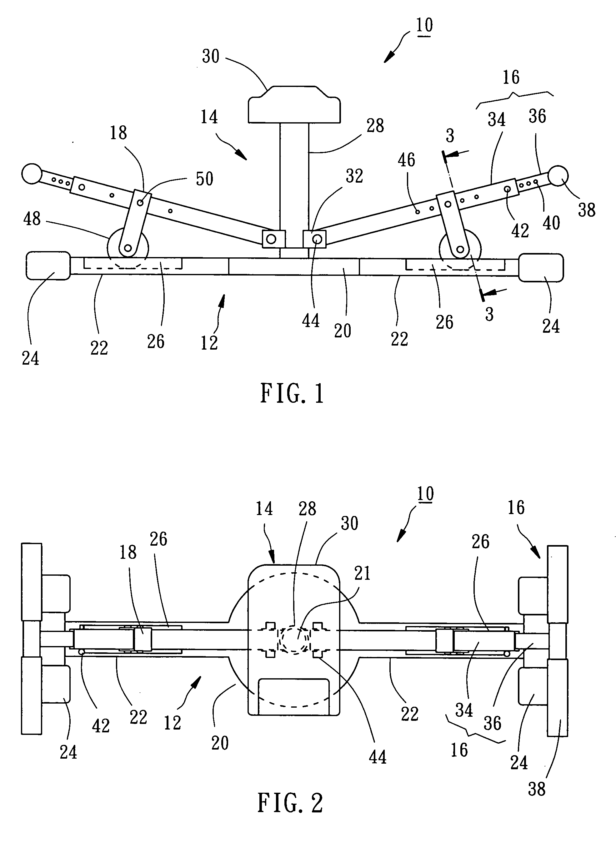
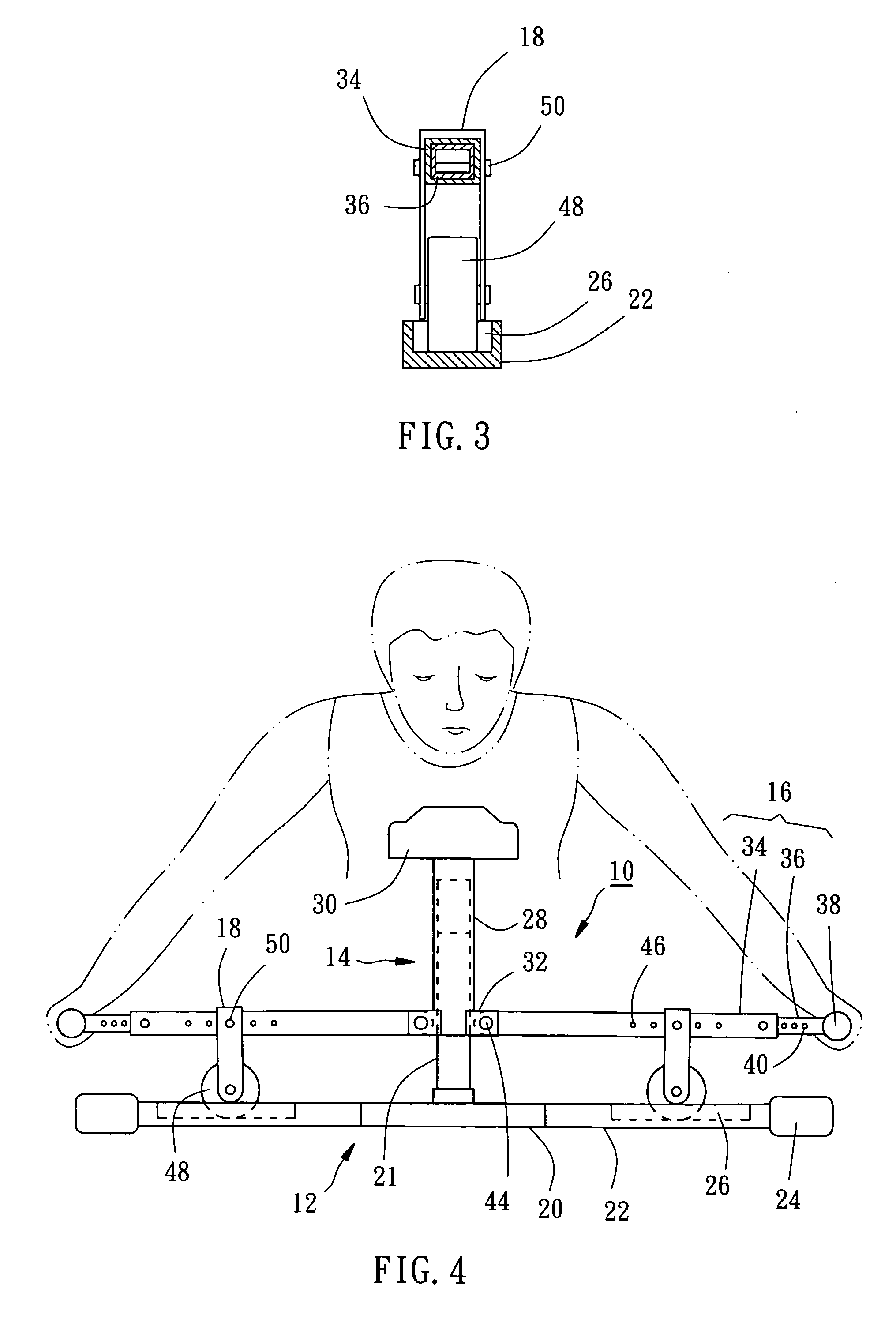
[0015] Referring to FIGS. 1-3, a push-up trainer 10 constructed according to a preferred embodiment of the present invention is comprised of a base 12, a supporter 14, two pressing bars 16, and two upholding members 18.

[0016] The base 12 is normally placed on the floor, including a circular chassis 20, an upright underprop 21 extending upwards from a top center of the chassis 20, two elongated bottom struts 22 formed at two opposite sides of an peripheral edge of the chassis 20, and two lateral struts 24 horizontally perpendicularly formed respectively at distal ends of the two bottom struts 22. Each of the bottom struts 22 is provided with a guide slot 26 recessed downwards from a top side thereof.

[0017] The supporter 14 includes a sleeve 28, a cushion 30 mounted on a top side of the sleeve 28, and two pivoting portions 32 respectively mounted at two opposite sides of an outer peripheral edge of a bottom side of the sleeve 28. The sleeve 28 is coaxially fitted to the underprop 21...


PUM


Abstract

A push-up trainer is comprised of a base having an underprop, a supporter movably mounted to the underprop of the base, two pressing bars each having an end pivotably mounted to the supporter, and two upholding members respectively detachably mounted to the pressing bars and each having a slidable member contacting against the base.

Description

BACKGROUND OF THE INVENTION [0001] 1. Field of the Invention [0002] The present invention relates generally to exercise apparatuses, and more particularly to a push-up trainer. [0003] 2. Description of the Related Art [0004] A conventional push-up trainer 80, as shown in FIG. 5, is comprised of an elongated base 81, a supporter 82, two pressing bars 83, and a guiding member 84. The elongated base 81 includes two upholding members 85 extending upwards. The supporter 82 includes a cushion 86 and two bearing bars 87 mounted to a bottom side of the cushion 86. Each of the two pressing bars 83 is pivotably connected to an apex of the upholding member 85, including an end pivotably mounted to a distal end of each bearing bar 87 and the other end provided with a handlebar 88. The guiding member 84 includes a first section 91 and a second section 92, which both are pivotably connected with each other to be collapsible relatively to each other. The guiding member 84 is mounted between the ba...

Claims


Application Information

Patent Timeline
IPC IPC(8): A63B21/068A63B23/035A63B23/12A63B26/00A63B71/00
CPCA63B23/1236A63B21/068
Inventor WEN, WEI-TZU
Owner WEN WEI TZU
Learn More