Electronic writing system and operating method thereof

a writing system and electronic writing technology, applied in the field of electronic writing systems, can solve the problems of user inconvenience, high cost of electronic writing systems with large sizes of resistance type or capacitor types, and unfriendly design for users, and achieve the effect of reducing operation inconvenien

Active Publication Date: 2015-04-28
AU OPTRONICS CORP
View PDF14 Cites 0 Cited by
  • Summary
  • Abstract
  • Description
  • Claims
  • Application Information

AI Technical Summary

Benefits of technology

[0010]In the electronic writing system of the present disclosure, a movable image eraser is utilized to generate the light with a mixture color of at least two of the first color, the second color and the third color for sending out an erasing signal to the display device, so as to remove the displayed image in the corresponding pixel region and enable the corresponding pixel region to display a blank image or a white image. Accordingly, when the user wants to erase a pattern, he does not need to switch to the eraser function by walking for a long distance for selecting the functional icon representing eraser function anymore, and the user could directly use the image eraser to remove the image displayed by the display device, so as to decrease the operation inconvenience.

Problems solved by technology

However, the cost of resistance type or capacitor type electronic writing systems with large sizes is very high, thus usually the optical type sensing method is mainly adopted in electronic writing systems with large sizes.
This makes the user inconvenient and the design is unfriendly for the user.
As a result, to solve the inconvenience problem of erasing image is still an issue for manufactures.

Method used


Image

  • Electronic writing system and operating method thereof
  • Electronic writing system and operating method thereof
  • Electronic writing system and operating method thereof

Examples


first embodiment

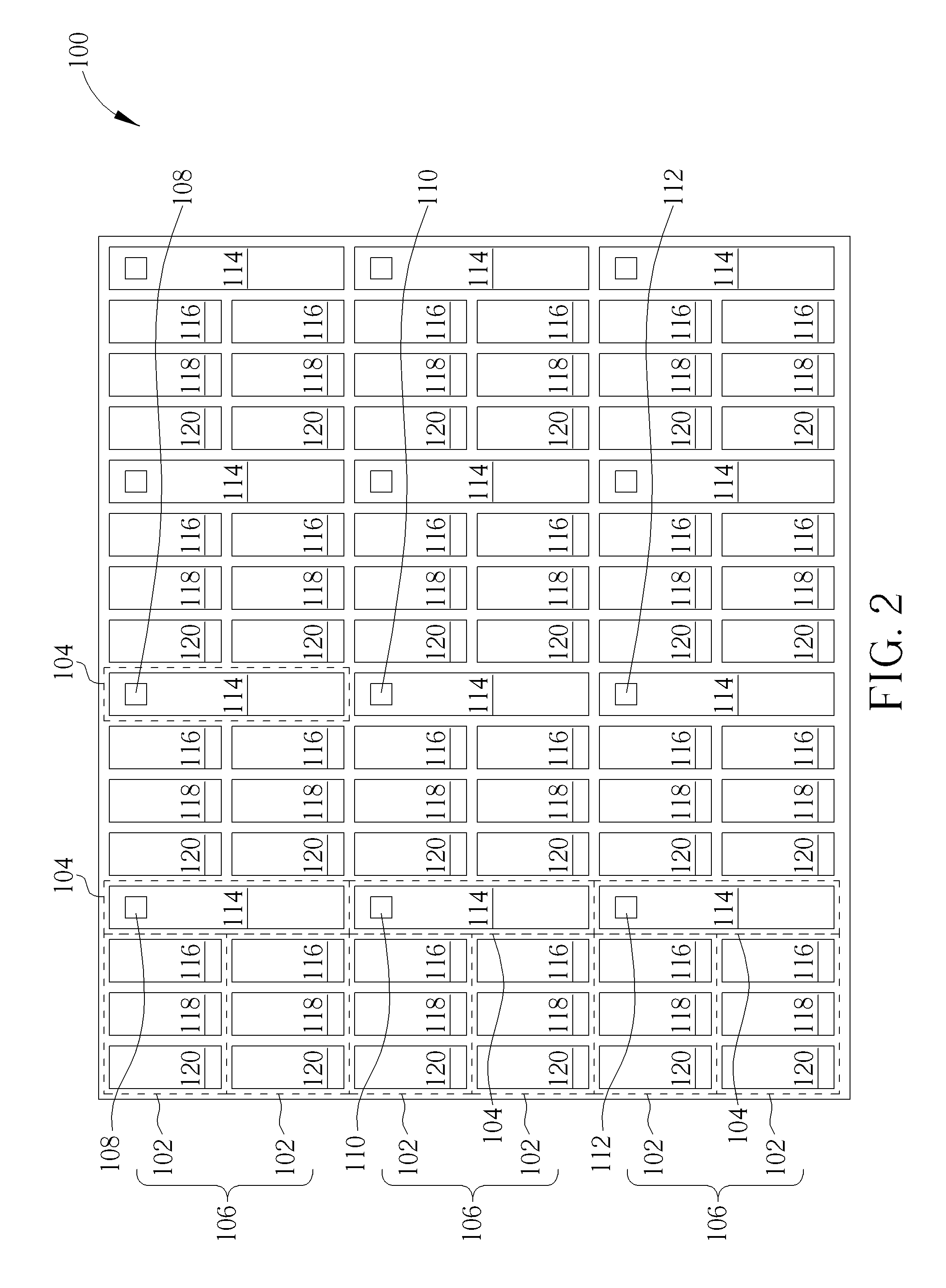
[0030]With reference to FIG. 3, FIG. 3 is a top-view schematic diagram of a display device of an electronic writing system according to a second preferred embodiment of the present disclosure. As shown in FIG. 3, in comparison with the display device of the first embodiment, each of the sensing regions 104 of the display device 200 of this embodiment is disposed in one of the fourth color filters 116 in its corresponding pixel region group 106, and each sensing region 104 does not have a transparent area. It should be noted that the fourth color filters 116 of this embodiment are blue color filters. Since human eyes have low sensitivity to blue light, disposing the sensing regions 104 in each fourth color filter 116 will not affect the color displayed by the display device 100 and can further effectively save the space for disposing the optical sensors in this embodiment.

[0031]In addition, based the aforementioned display device, the present disclosure further provides an image eras...

third embodiment

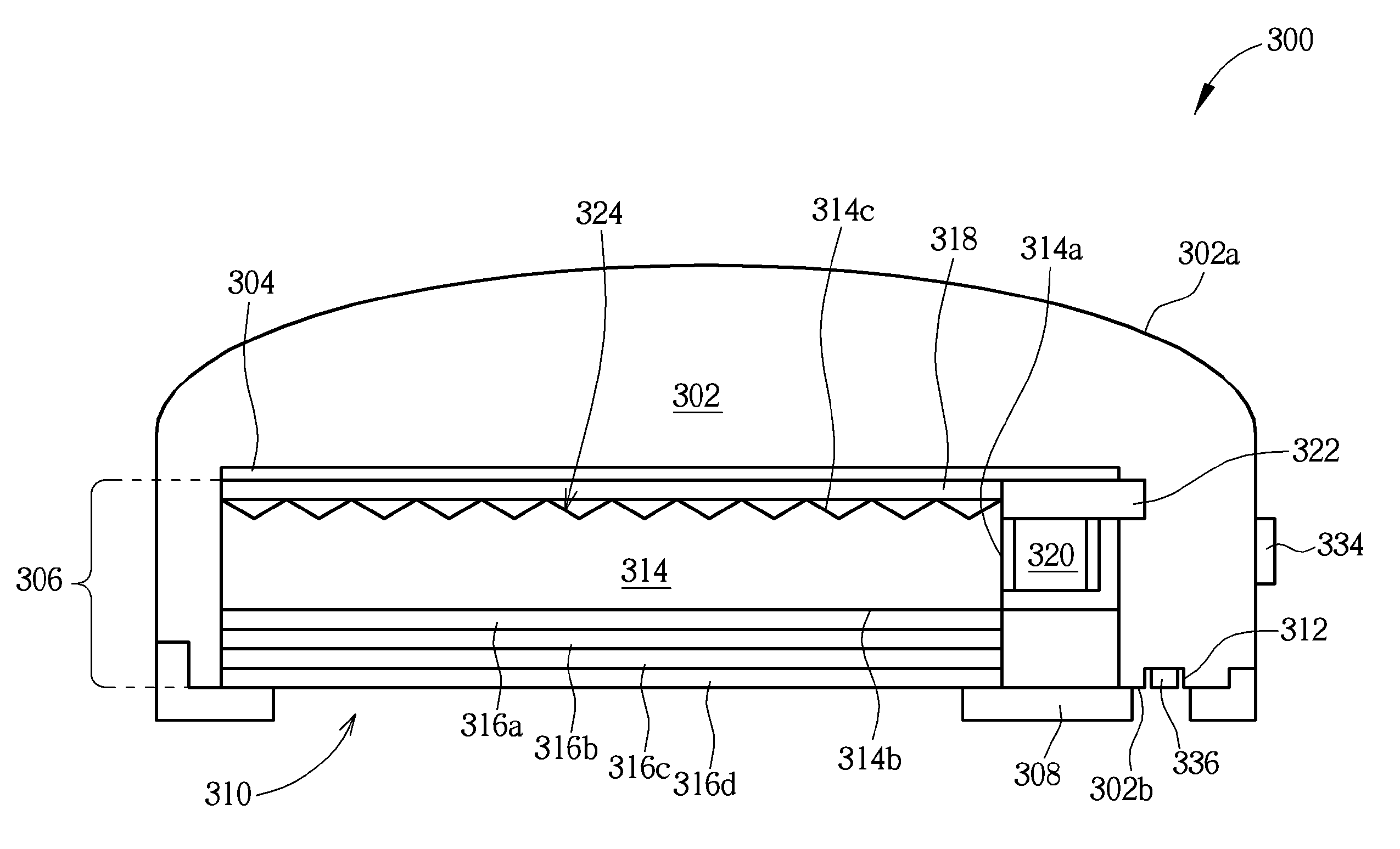
[0037]With reference to FIG. 7, FIG. 7 is a sectional schematic diagram of an image eraser of an electronic writing system according to a fourth preferred embodiment of the present disclosure. As shown in FIG. 7, in comparison with the third embodiment, the light entrance surface 314a and the light exit surface 314b of the LGP 314 are parallel with and face to each other in the image eraser 400 of this embodiment, which means the light entrance surface 314a is the bottom surface of the LGP 314 and the light source 320 is disposed between the holder 302 and the LGP 314. Furthermore, the bottom surface of the LGP 314 of this embodiment does not have micro structures, but not limited thereto.

[0038]With reference to FIG. 8, FIG. 8 is a sectional schematic diagram of an image eraser of an electronic writing system according to a fifth preferred embodiment of the present disclosure. As shown in FIG. 8, in comparison with the third embodiment, the image eraser 600 is a two-sided light-emit...


PUM


Abstract

The present disclosure provides an electronic writing system including a holder, a light guide plate, at least one light source, and at least one optical film. The light guide plate is disposed in the holder, and the light guide plate has at least one light entrance surface and a light exit surface. The light source is disposed on the light entrance surface of the light guide plate, and is used for generating a light. The light enters the light guide plate through the light entrance surface, and the light emits out of the light guide plate from the light exit surface. The optical film covers the light exit surface of the light guide plate.

Description

BACKGROUND OF THE DISCLOSURE[0001]1. Field of the Disclosure[0002]The present disclosure is related to an electronic writing system and an operation method thereof.[0003]2. Description of the Prior Art[0004]Conventional electronic writing system is composed of a display, such as a liquid crystal display (LCD), and a touch-control pen, such as a light pen, and the display needs to have a sensing device for sensing the input signal from the touch-control pen. The electronic writing system can be classified into resistance type, capacitor type and optical type electronic writing systems according to the sensing method. However, the cost of resistance type or capacitor type electronic writing systems with large sizes is very high, thus usually the optical type sensing method is mainly adopted in electronic writing systems with large sizes.[0005]With reference to FIG. 1, FIG. 1 is a schematic diagram of a conventional optical type electronic writing system having a large size. As shown i...

Claims


Application Information

Patent Timeline
Patent Type & Authority Patents(United States)
IPC IPC(8): G06F3/0354G06F3/03G06F3/038G06F3/041G06F3/042
CPCG06F3/0321G06F3/0386G06F3/0412G06F3/042G06F3/03542
Inventor CHANG, WEI-TIENTSAI, SHAU-YU
Owner AU OPTRONICS CORP
Why Eureka
Try Eureka