
Pistol with firing pin locking mechanism

Active Publication Date: 2005-10-20
STURM RUGER & CO INC
View PDF42 Cites 42 Cited by
  • Summary
  • Abstract
  • Description
  • Claims
  • Application Information

AI Technical Summary

Benefits of technology

[0004] A firing pin locking mechanism for a pistol is provided that includes a stopping member which may be selectively moved by a user of the pistol between first and second positions, and a movable blocking member that may be engaged with a forwardly-movable firing pin to prevent the firing pin from striking a loaded cartridge to discharge the pistol. In a first activated position, the stopping member prevents the firing pin blocking member from being operably disengaged from the firing pin, thereby preventing the firing pin from moving forward to strike a chambered cartridge. In the second deactivated position, the stopping member allows the firing pin blocking member to be disengaged from the firing pin by normal operation of the pistol trigger system to allow the pistol to be discharged. In a preferred embodiment, the same firing pin locking mechanism also provides a trigger block to prevent a user of the pistol from being able to fully pull the trigger rearwards as when discharging the pistol.
[0010] In another embodiment, the firing pin locking mechanism may further include a movable selector member that preferably is mechanically connected to the stopping member and controls the movement and position of the stopping member. The selector member is preferably manually operated by a user of the pistol. In one embodiment, the selector member may be a rotatable selector switch that controls the position of the stopping member. Accordingly, the stopping member preferably moves concomitantly with the movement of the selector member. In yet another embodiment, the selector member may be configured as a thumb-lever mechanism that is supported by the pistol housing. At least one thumb-lever is preferably provided. More preferably, the thumb-lever mechanism is a dual or ambidextrous mechanism having two thumb-levers with one thumb-lever preferably being located on either side of the pistol. In one embodiment, the stopping member is pivotally connected to the thumb-lever mechanism such that the rotational movement of the thumb-lever is translated into axial movement of the stopping member. The thumb-lever mechanism may be movable from a first “ready-to-fire” position in which the stopping member does not engage the blocking member to a second “safe” (locked) position in which the stopping member engages and prevents movement of the firing pin blocking member.

Problems solved by technology

These automatic devices, however, do not provide a pistol user with the ability to manually lock the device in the blocking position engaged with the firing pin.

Method used


Image

  • Pistol with firing pin locking mechanism
  • Pistol with firing pin locking mechanism
  • Pistol with firing pin locking mechanism

Examples


Embodiment Construction

[0079] A preferred embodiment of a firing pin locking mechanism for a pistol will now be described for convenience with reference and without limitation to a centerfire-type pistol in the form of an auto-loading pistol that uses centerfire cartridges (i.e., primer located in center of base of cartridge). It will be appreciated that other embodiments of the firing pin locking mechanism may be made that are suitable for use with other type pistols.

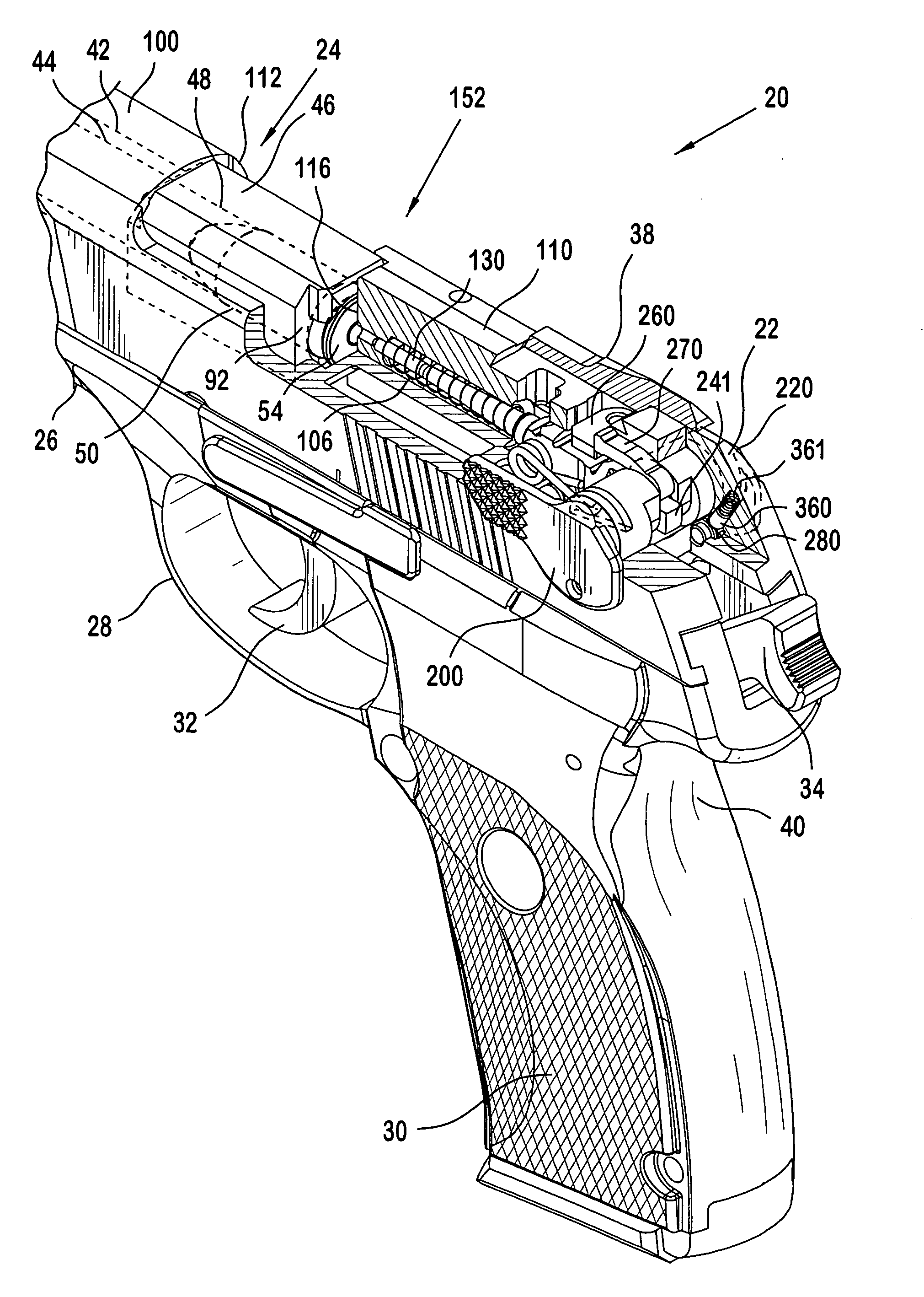
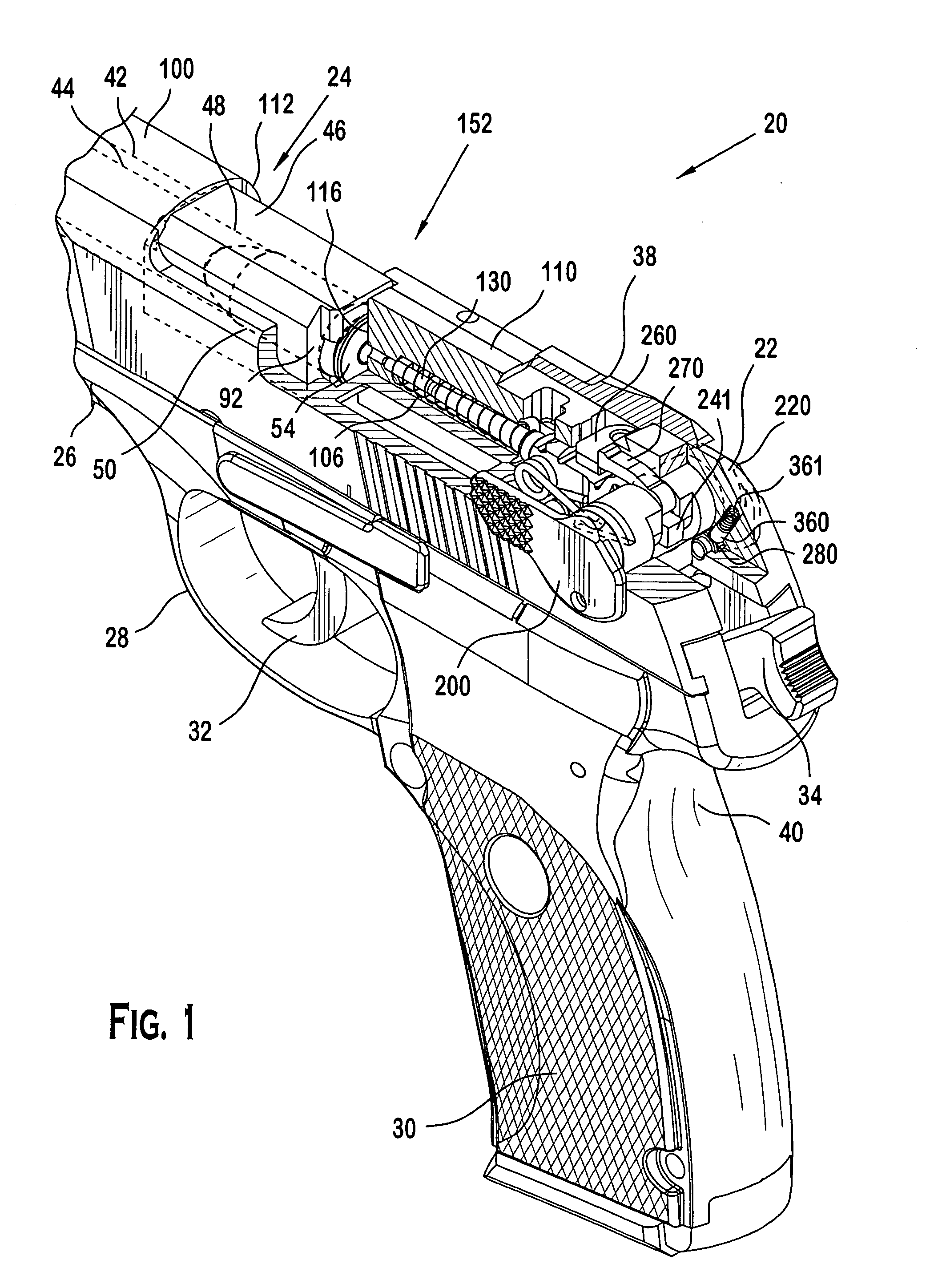
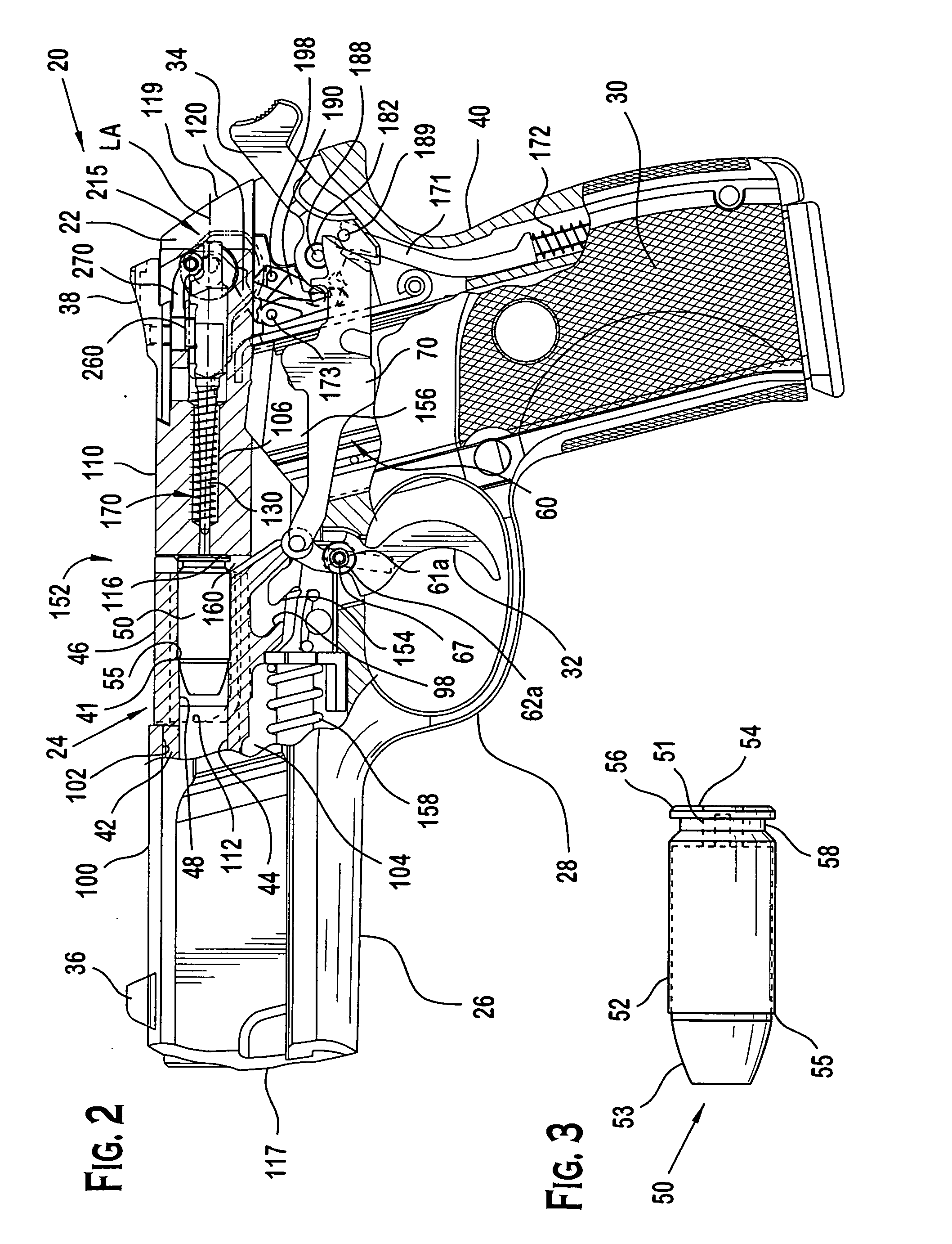
[0080] Referring particularly to FIGS. 1-2, a pistol 20 generally includes: a housing such as slide 22; a longitudinally-extending barrel unit 24; a frame 26 including a trigger guard 28, grip frame 40 and a hand grip 30 mounted thereon; a firing pin 130; a trigger 32; a hammer 34; a front sight 36; and a rear sight 38. Grip frame 40 may hold a removable magazine 156 with spring-loaded follower which is capable of holding and dispensing a plurality of cartridges for automatic loading of pistol 20.

[0081] With additional reference to FIG. 7,...


PUM


Abstract

A pistol including a mechanism that locks firing pin of the pistol. The firing pin locking mechanism may include a stopping member which may be selectively moved by a user of the pistol between first and second positions, and a movable blocking member that may be engaged with a forwardly-movable firing pin. A biasing member such as a spring may be provided to bias the blocking member into engagement with the firing pin. In one embodiment, the blocking member arrests or blocks the forward motion of the firing pin to prevent the firing pin from striking a loaded cartridge and discharging the pistol. In a possible first activated position, the stopping member prevents the firing pin blocking member from being operably disengaged from the firing pin, thereby preventing the firing pin from moving forward to strike a cartridge. In a possible second deactivated position, the stopping member allows the firing pin blocking member to be disengaged from the firing pin by normal operation of the pistol trigger system to allow the pistol to be discharged. The firing pin locking mechanism may further include a locking member to allow a pistol user to lock the stopping member in the first position or second position.

Description

BACKGROUND OF THE INVENTION [0001] The present invention generally relates to firearms, and more particularly to a mechanism related to locking the firing pin of a pistol. [0002] Prior devices for pistols are known that engage and arrest the forward movement of the firing pin so that it cannot strike a cartridge loaded in the chamber without pulling the trigger. In one type of known device, a spring-biased pin or plunger is provided that moves in a reciprocating manner into and out of engagement with the firing pin. When in a blocking position and absent a trigger pull, the device is spring-biased into engagement with the firing pin to prevent it from being moved forward and striking the cartridge. When the trigger is pulled to discharge the pistol, a mechanical release moves the device against the spring force to a position disengaged from the firing pin. The firing pin may now freely move forward in response to being struck at the rear by the hammer to strike a loaded cartridge an...

Claims


Application Information

Patent Timeline
IPC IPC(8): F41A17/02F41A17/72
CPCF41A17/72F41A17/02
Inventor MCGARRY, JAMES
Owner STURM RUGER & CO INC
Learn More