Fuel supply apparatus

a technology of fuel supply and fuel pipe, which is applied in the direction of liquid fuel feeders, machines/engines, combustion air/fuel air treatment, etc., can solve the problems of deteriorating the free movement of fuel pipes, deteriorating the outer appearance, and exposing the fuel communication pipes from the side portion of two-wheel vehicles, etc., to improve the stability of fuel injection and excellent particularly in mounting

Inactive Publication Date: 2005-10-20
KEIHIN CORP
View PDF3 Cites 11 Cited by
  • Summary
  • Abstract
  • Description
  • Claims
  • Application Information

AI Technical Summary

Benefits of technology

[0033] The present invention is made by taking the problems mentioned above into consideration, and a main object of the present invention is to inhibit vapor from being generated in fuel flowing within a fuel communicating pipe by making a pipe length of the fuel communicating pipe as short as possible, thereby improving a stability of fuel injected from a fuel injection valve, and the other object of the present invention is to provide a fuel supply apparatus which does not require any specific protecting member to the fuel communicating pipe, is improved in freedom of arranging the fuel communicating pipe, and is excellent particularly in mounting to a two-wheel vehicle.

Problems solved by technology

(2) Particularly in the case of being used as the fuel supply apparatus in which the receiving space of the apparatus is largely limited in comparison with a four-wheel vehicle, such as that for a two-wheel vehicle, there is a risk that the fuel communicating pipe 103 interferes with the other constituting members such as a frame, a tank or the like, so that a freedom of arranging the fuel pipe is deteriorated.
(3) Particularly in the case of being used in the structure in which the fuel supply apparatus is directly exposed to the exterior, such as that for the two-wheel vehicle, a protecting member is necessarily provided so as to prevent the fuel communicating pipe 103 and the passenger from being in contact with each other or prevent the fuel communicating pipe from being brought into contact with the other member, and there is a risk that the fuel communicating pipe exposes from the side portion of the two-wheel vehicle so as to deteriorate an outer appearance.

Method used


Image

  • Fuel supply apparatus
  • Fuel supply apparatus
  • Fuel supply apparatus

Examples


Embodiment Construction

[0085] A description will be given below of an embodiment of a fuel supply apparatus in accordance with the present invention.

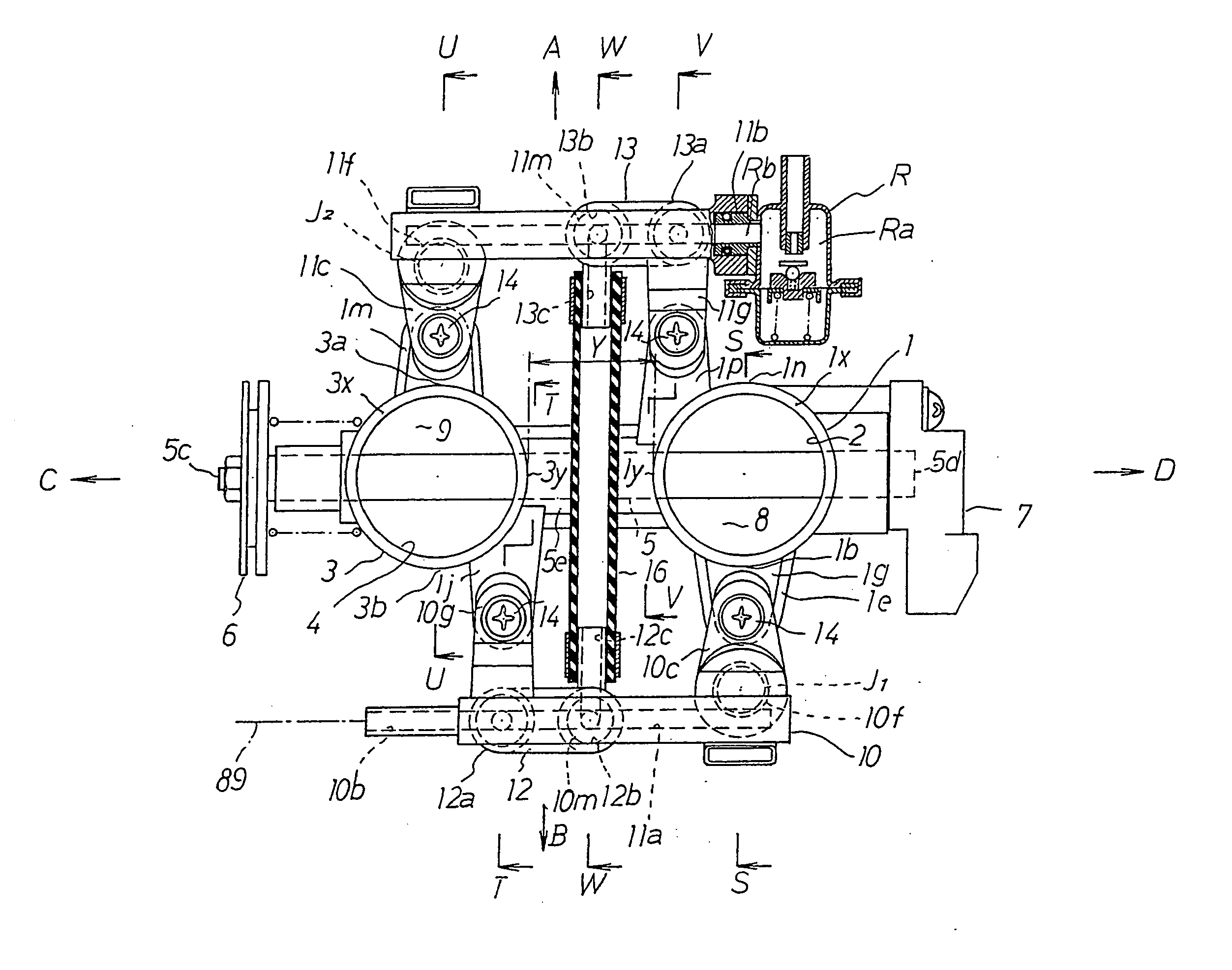
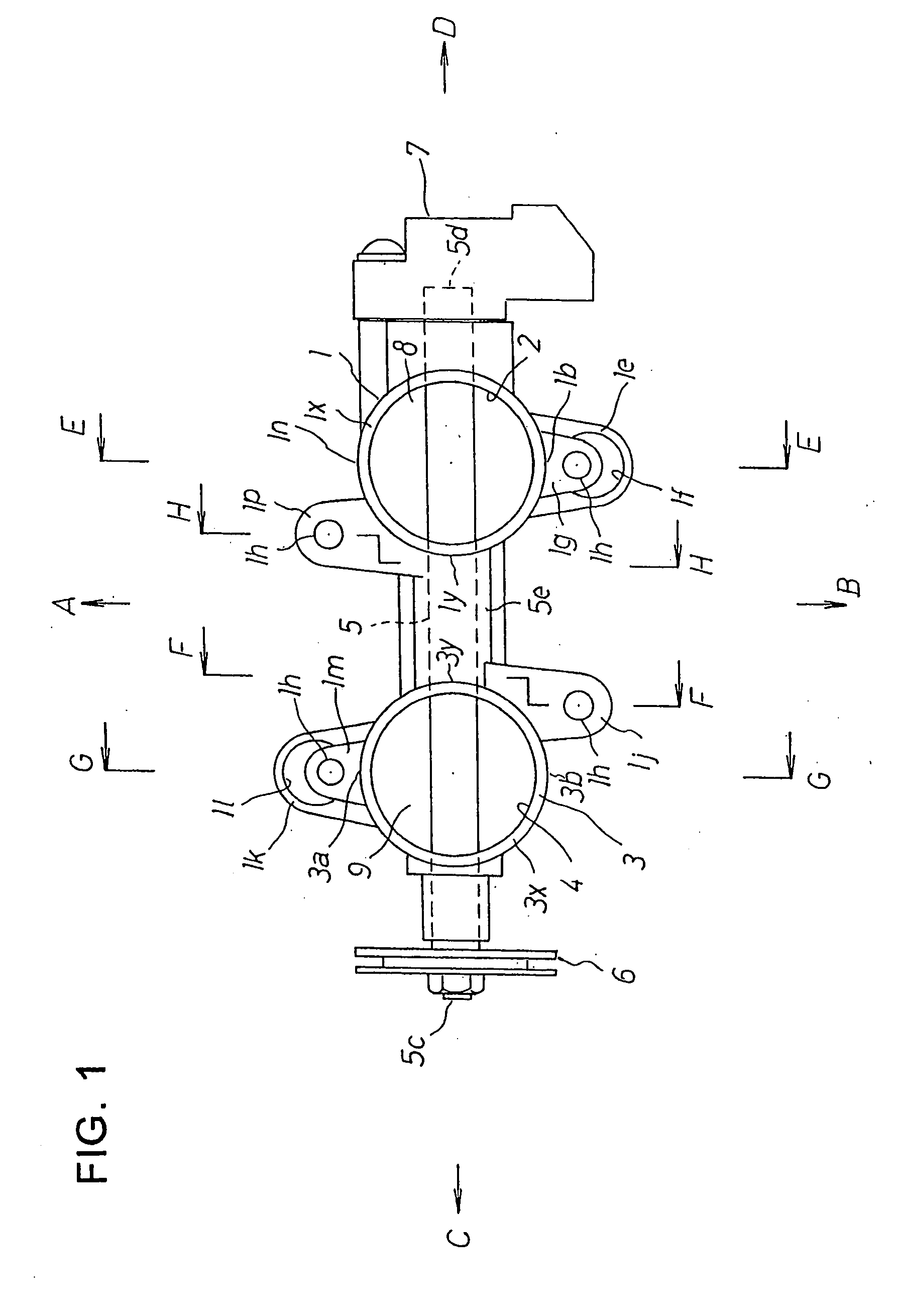
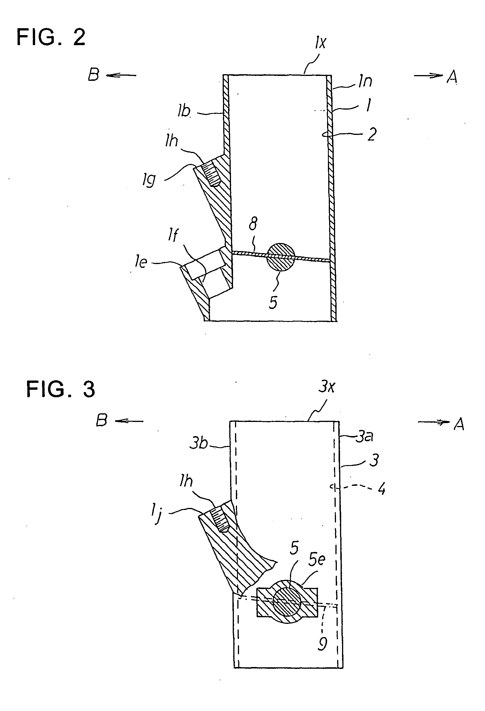
[0086]FIG. 1 is a plan view of an upper portion of a throttle body, FIG. 2 is a vertical cross sectional view along a line E-E in FIG. 1, FIG. 3 is a vertical cross sectional view along a line F-F in FIG. 1, FIG. 4 is a vertical cross sectional view along a line G-G in FIG. 1, and FIG. 5 is a vertical cross sectional view along a line H-H in FIG. 1.

[0087] Reference numeral 1 denotes a first throttle body in which a first intake path 2 is provided through in a vertical direction. A first injection valve inclined end surface 1e is formed in one side outer surface 1b of the first throttle body 1, whereby a first injection valve support hole 1f is provided through in an oblique direction toward a center of the first intake path 2.

[0088] Further, a first supply body inclined end surface 1g is formed in the one side outer surface 1b of the first throttle body 1 ...


PUM


Abstract

To inhibit vapor in a fuel flowing to a second fuel distribution path by shortening a fuel communicating pipe between first and second fuel distribution paths in respective sides of a throttle body, first and second throttle bodies (1, 3) are arranged in parallel, first and second throttle valves (8, 9) are attached to a single throttle valve shaft (5), a throttle drum (6) is attached to a left end (5c) of the throttle valve shaft (5), first and second fuel supply bodies (10, 11) including first and second fuel injection valves (J1, J2) are arranged respectively in one side (B) and the other side (A) of the throttle bodies, both the fuel supply bodies (10, 11) are connected by a fuel communicating path (16), and the fuel communicating path (16) is arranged inn a space among throttle valve shaft (5), upper ends (1x, 3x) of the throttle bodies, opposing side surfaces of both the throttle bodies (1, 3).

Description

TECHNICAL FIELD [0001] The present invention relates to a fuel supply apparatus for supplying a fuel to an internal combustion engine, and more particularly to a fuel supply apparatus in a fuel injection type which injects and supplies fuel having pressure increased by a fuel pump toward inner sides of a plurality of intake pipes by a plurality of fuel injection valves. BACKGROUND ART [0002] A conventional fuel supply apparatus using a fuel injection valve is shown in FIGS. 22 and 23. [0003]FIG. 22 is an upper plan view in the case of seeing a fuel supply apparatus from the above, and FIG. 23 is a vertical cross sectional view of a main portion in a line Z-Z of FIG. 22. [0004] Reference numeral 80 denotes a first throttle body in which a first intake path 81 is provided therethrough in a vertical direction, in FIG. 23. The first intake path 81 is opened and closed by a first throttle valve 83 attached to a first throttle valve shaft 82. [0005] An upper opening 81a of the first intak...

Claims


Application Information

Patent Timeline
Patent Type & Authority Applications(United States)
IPC IPC(8): F02M37/00F02D9/02F02D9/10F02M35/10F02M55/02F02M63/00F02M69/00F02M69/04F02M69/46F02M69/54
CPCF02D9/1095F02M35/10216F02M2200/40F02M69/465F02M69/54F02M69/044
Inventor TAGUCHI, NAOHIRO
Owner KEIHIN CORP
Why Eureka
Try Eureka