

Sliding roof system
- Summary
- Abstract
- Description
- Claims
- Application Information
AI Technical Summary
Benefits of technology
Problems solved by technology
Method used
Image

Examples
Embodiment Construction
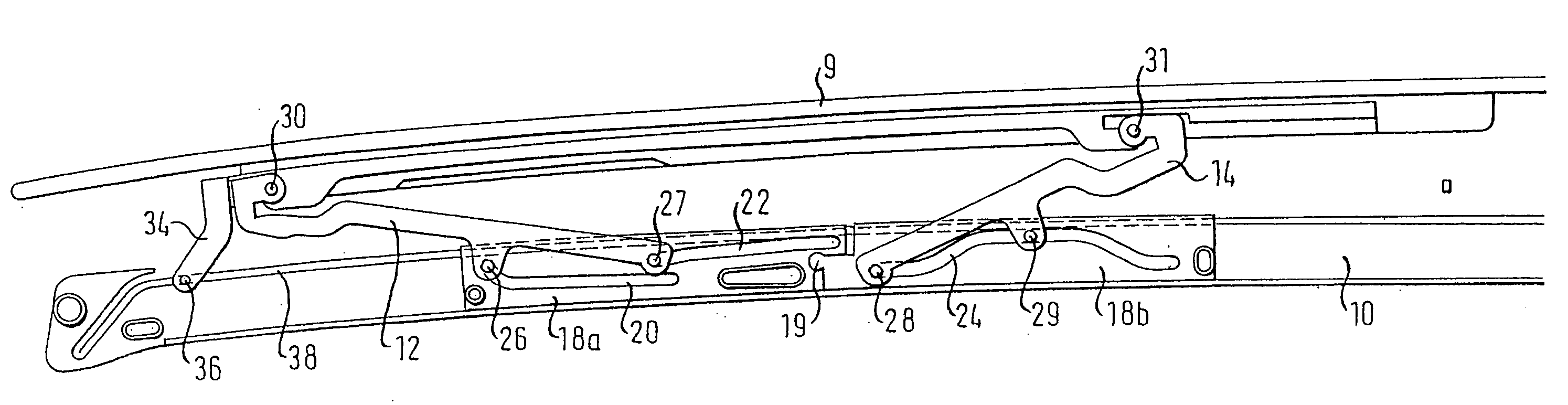
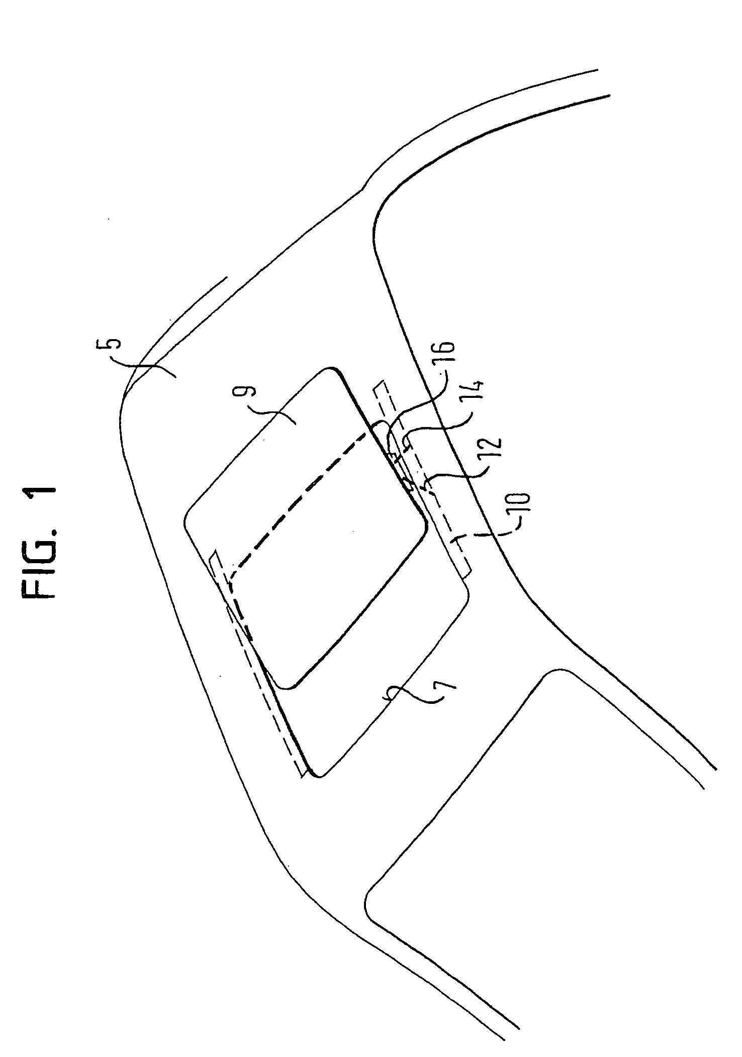
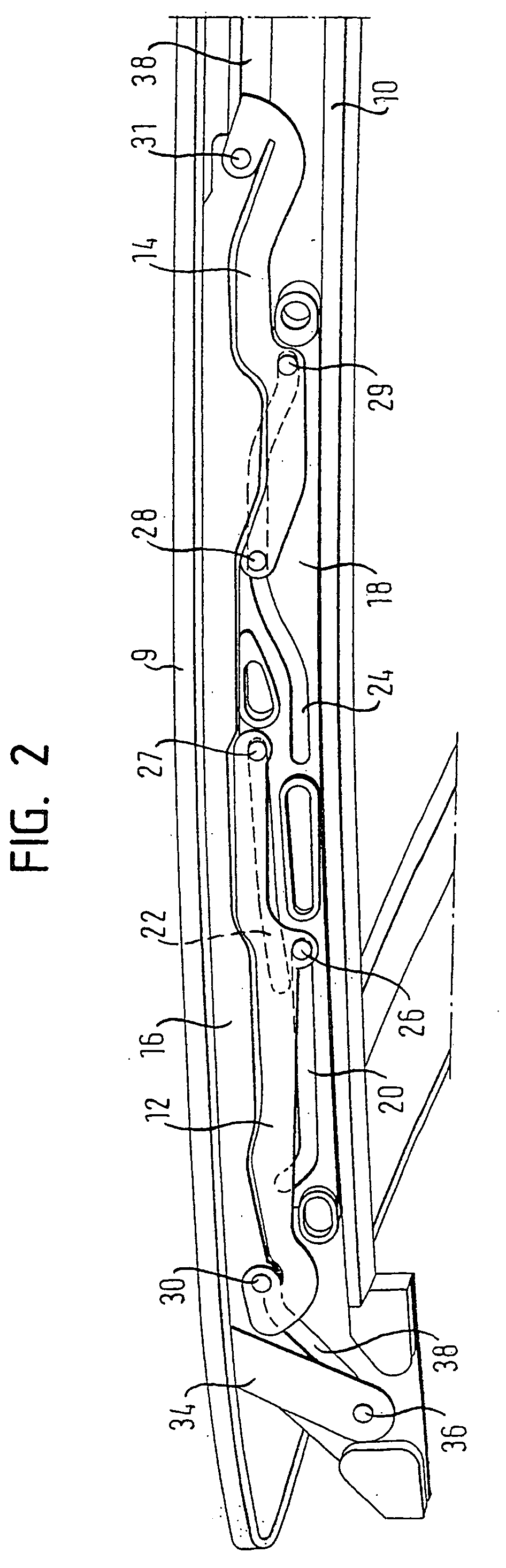
[0022]FIG. 1 shows a vehicle roof 5 with an opening 7. Associated with the opening 7 is a cover 9 that can be moved between a closed position in which the cover 9 closes the opening 7, and an open position that at least partially exposes the opening 7. Associated with the cover 9 is a sliding roof system, the essential components of which include two guide rails 10, first and second lifting levers 12, 14, and two cover supports 16. The cover supports 16 are configured as separate components that are fixedly mounted to the cover 9. Nevertheless, the cover supports 16 may also be constituted by inlay parts, which are embedded in the cover 9, or constituted by fastening tabs that are formed in one piece with the cover 9, etc.
[0023] The two guide rails 10 extend along longitudinal edges of opening 7, i.e., extend along a longitudinal direction of travel of a vehicle, from front to rear. Usually the guide rails 10 are formed by a section made of an aluminum alloy. A carriage 18 (see FIG...
PUM
 Abstract
Description
Claims
Application Information