
Pointing device

a pointing device and pointing technology, applied in the direction of mechanical pattern conversion, instruments, cathode-ray tube indicators, etc., can solve the problems of nausea, giddiness, and the like, and do not contribute to the large reduction of burden, so as to reduce a large burden on the eye

Inactive Publication Date: 2005-10-20
YAMAHA CORP
View PDF1 Cites 12 Cited by
  • Summary
  • Abstract
  • Description
  • Claims
  • Application Information

AI Technical Summary

Benefits of technology

[0006] The present invention has been made in view of the above-mentioned circumstances, and it is an object of the present invention to provide a pointing device capable of reducing largely a burden on the eye imposed by the pointing operation.
[0039] As described above, according to the present invention, a burden on the eye imposed by the pointing operation can be reduced largely.

Problems solved by technology

In this case, there existed such a problem that, if such pointing operation is executed continuously for a long time, symptoms such as nausea, giddiness, and the like appear because the user overworks his or her eyes excessively.
In the end, there existed such a problem that the above related arts do not contribute to the large reduction in the burden on the eye imposed by the pointing operation.

Method used


Image

  • Pointing device
  • Pointing device
  • Pointing device

Examples


Embodiment Construction

[0053] Embodiments according to the present invention will be explained with reference to the drawings hereinafter.

[0054] A. Present Embodiment

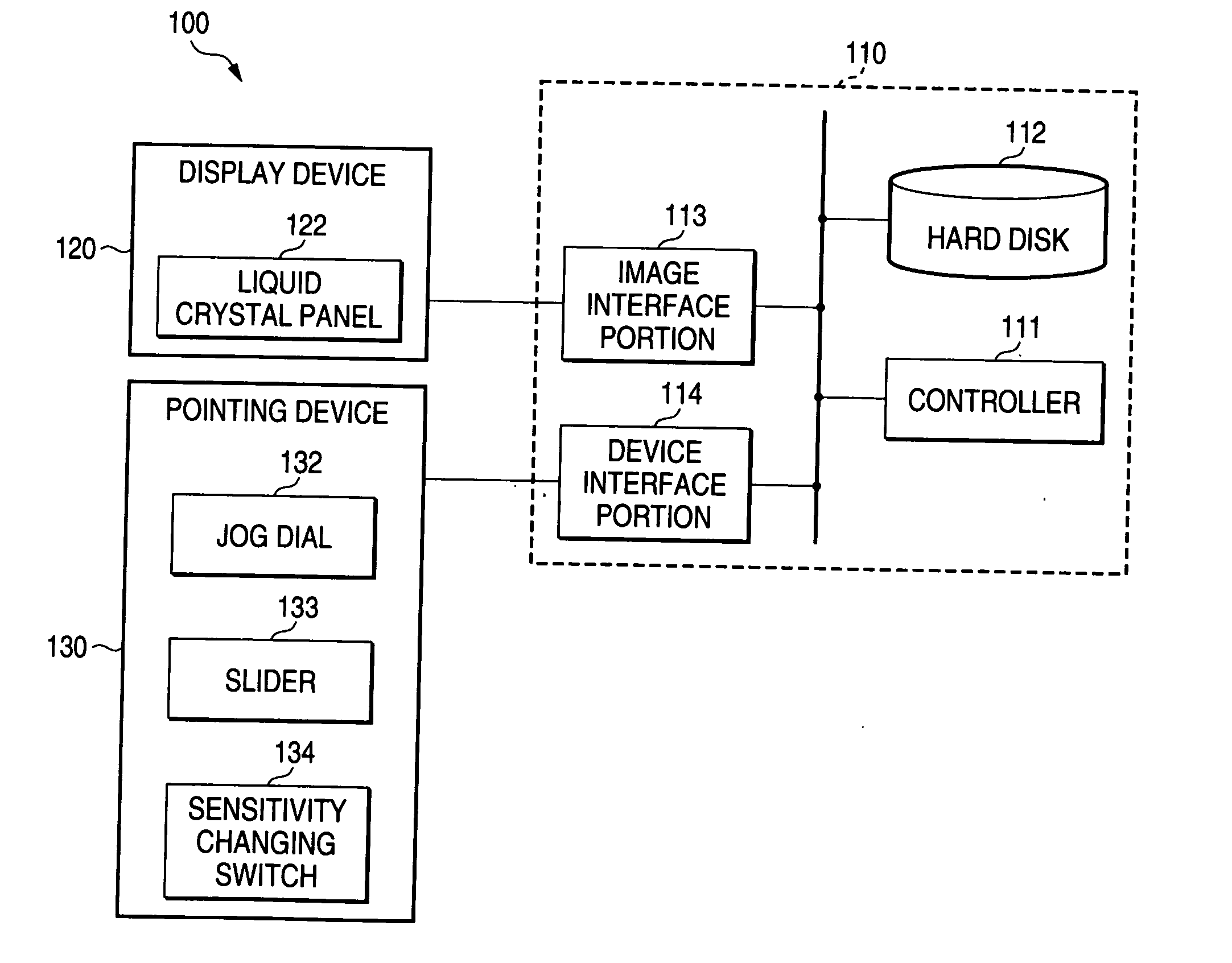
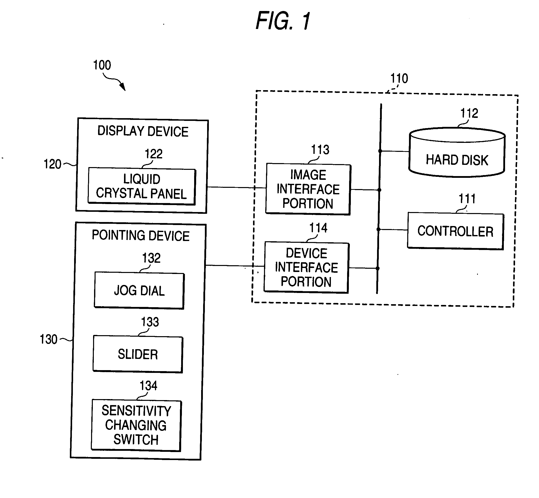
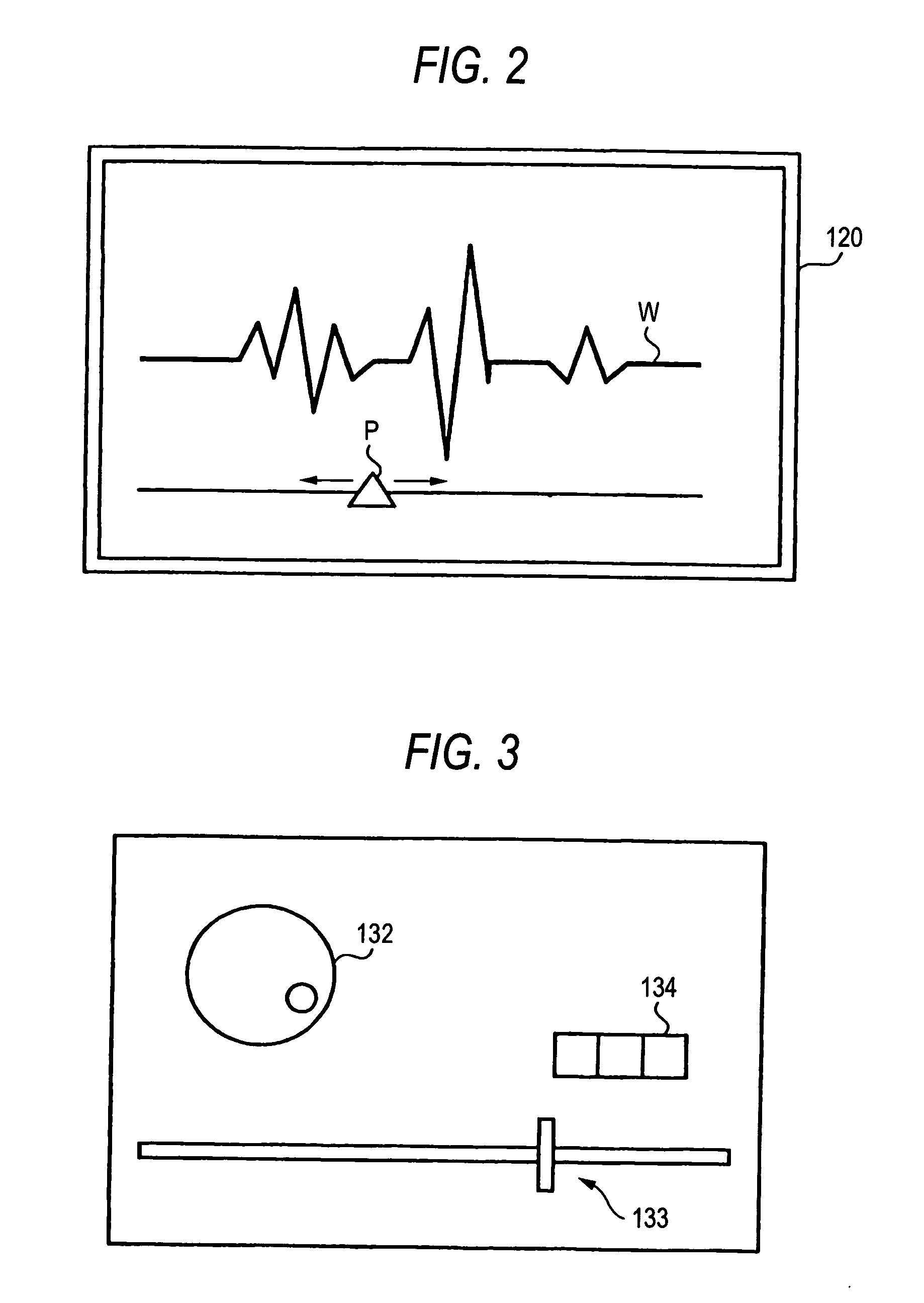
[0055]FIG. 1 is a view showing a configuration of an audio editing system 100 according to the present embodiment. The audio editing system 100 comprises a main unit 110 for collectively controlling respective portions of the audio editing system 100, a display device 120 (see FIG. 2) for displaying a musical sound waveform W, a pointer P, etc. in accordance with respective data supplied from the main unit 110, etc., a pointing device 130 (see FIG. 3) for moving the pointer P displayed on the display device 120, and a musical sound generating unit (not shown) for generating the musical sound based on musical sound waveform data corresponding to the musical sound waveform W.

[0056] As well known, upon editing the musical sound waveform, the designation of a particular point of the musical sound waveform (that is, finding the beginning or the...


PUM


Abstract

A sensing encoder fitted to a jog dial senses a rotation direction and a rotation amount of a dial and supplies the sensed result to a controller as operation information. A pointer moving unit, when receives the operation information, decides a position of the pointer based on the operation information and sends a moving instruction to a display device. At the same time, the pointer moving unit reads a value of the data pointed by the moved pointer from a hard disk, and then supplies this value to a vibration controlling unit. The vibration controlling unit controls a vibration generated by a vibration generating actuator in response to the value of the data that are received from the pointer moving unit.

Description

BACKGROUND OF THE INVENTION [0001] The present invention relates to a pointing device used to move a pointer displayed on a display device. [0002] As the operating device used to move a position of the pointer that is being displayed on the display device such as a display, various operating devices such as mouse, slider, jog dial, touch panel, and so on are employed. For example, when the computer in which the mouse is used as the operating device is utilized, the user moves the position of the pointer to a desired position by operating the mouse while gazing at the pointer displayed on the display device. [0003] In this manner, in order to move the position of the pointer displayed on the display device to a desired position by using the operating device, such as mouse, the user has to operate the operating device while looking carefully at the display screen (an operation of moving the pointer is referred to as a “pointing operation” hereinafter). In this case, there existed such...

Claims


Application Information

Patent Timeline
Patent Type & Authority Applications(United States)
IPC IPC(8): G06F3/00G06F3/01G06F3/033G06F3/0362G06F3/0487G09G5/00
CPCG06F3/0362G06F3/016
Inventor TADA, YUKIO
Owner YAMAHA CORP
Learn More