Protective sleeve structure for a portable electric product

Inactive Publication Date: 2005-10-20
APLUX COMM
View PDF10 Cites 34 Cited by
  • Summary
  • Abstract
  • Description
  • Claims
  • Application Information

AI Technical Summary

Benefits of technology

[0009] The object of present invention is to provide a protective sleeve structure for a portable electric product which uses a support-plate with features of sticking and pivotal-lift to flatly stick with the second body so the placement of the electric product is not affected by the support-plate. If the user want to use the electric product, the support-plate can be pivotal-lifted with a certain angle and the bottom end of the support-plate can be linked up with the bottom surface of the first body at appropriate position such that the support-plate keeps inclined and the front portion of the first body forms a space for standing the electric product, thus the user can operate the electric product anytime and anywhere, and not limited by the environment.
[0010] The another object of the present invention is to provide a protective sleeve structure for a portable electric product wherein the heat generated from the electric product leaned upon the support-plate can be fast diffused through the permeable-net installed on the support-plate such that the temperature of the electric product can be reduced.
[0011] A protective sleeve structure for a portable electric product according to the present invention capable of achieving the above-mentioned objects comprises a protective sleeve and a support-plate. The protective sleeve mainly includes a first body and a second body. A sticking-layer is paved with each bottom surface of the first body and the second body, and a zipper is

Problems solved by technology

Contained in the conventional sleeve, the electric product cannot be operated, or the heat generated from the running product cannot be diffused smoothly as the sleeve coating the electric product even the product can be operated.
Operating under high temperature, it is possible that the electric product may have a breakdown or its components may be damaged.
Since the heat cannot be diffused from the back

Method used


Image

  • Protective sleeve structure for a portable electric product
  • Protective sleeve structure for a portable electric product
  • Protective sleeve structure for a portable electric product

Examples


Example

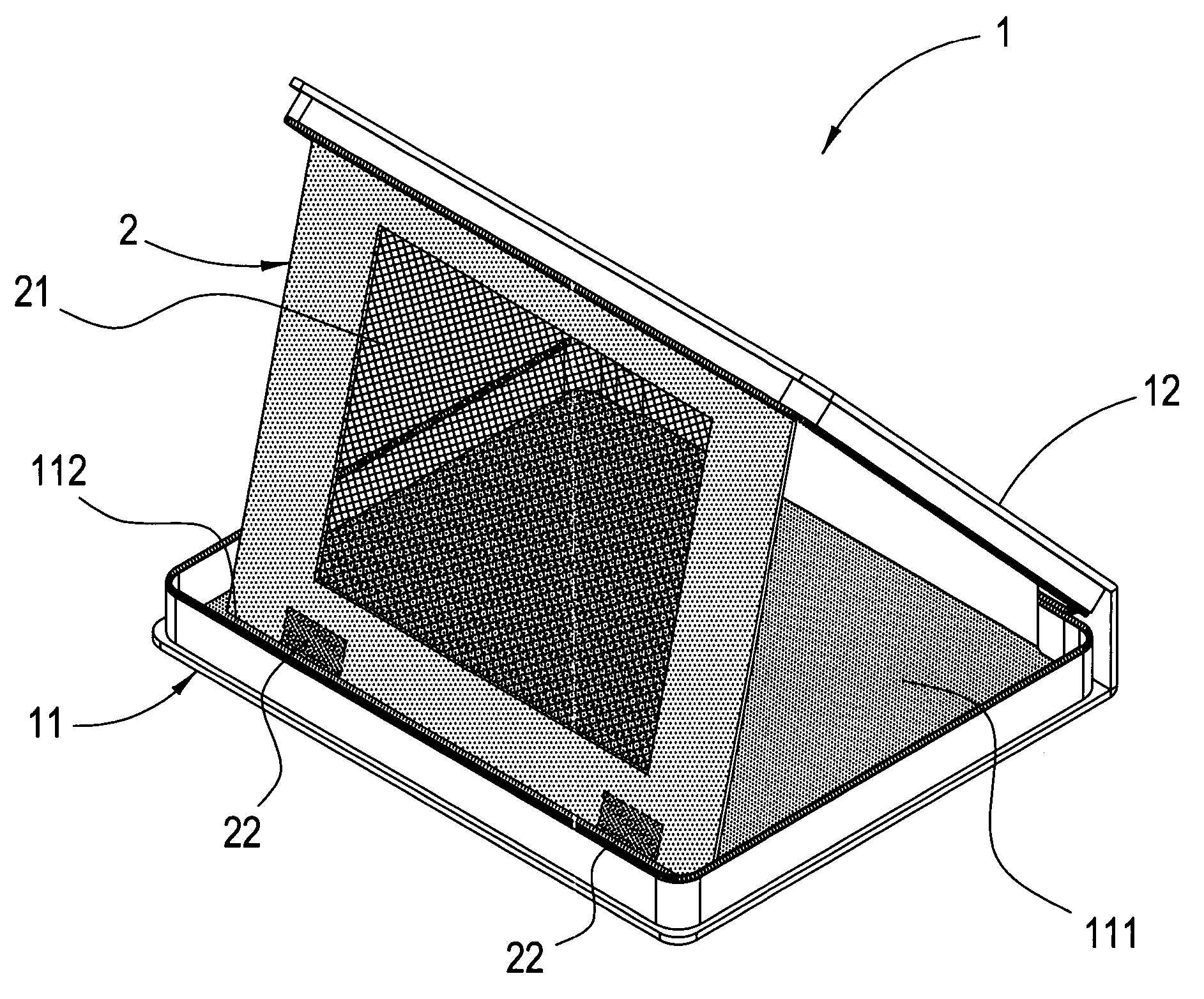
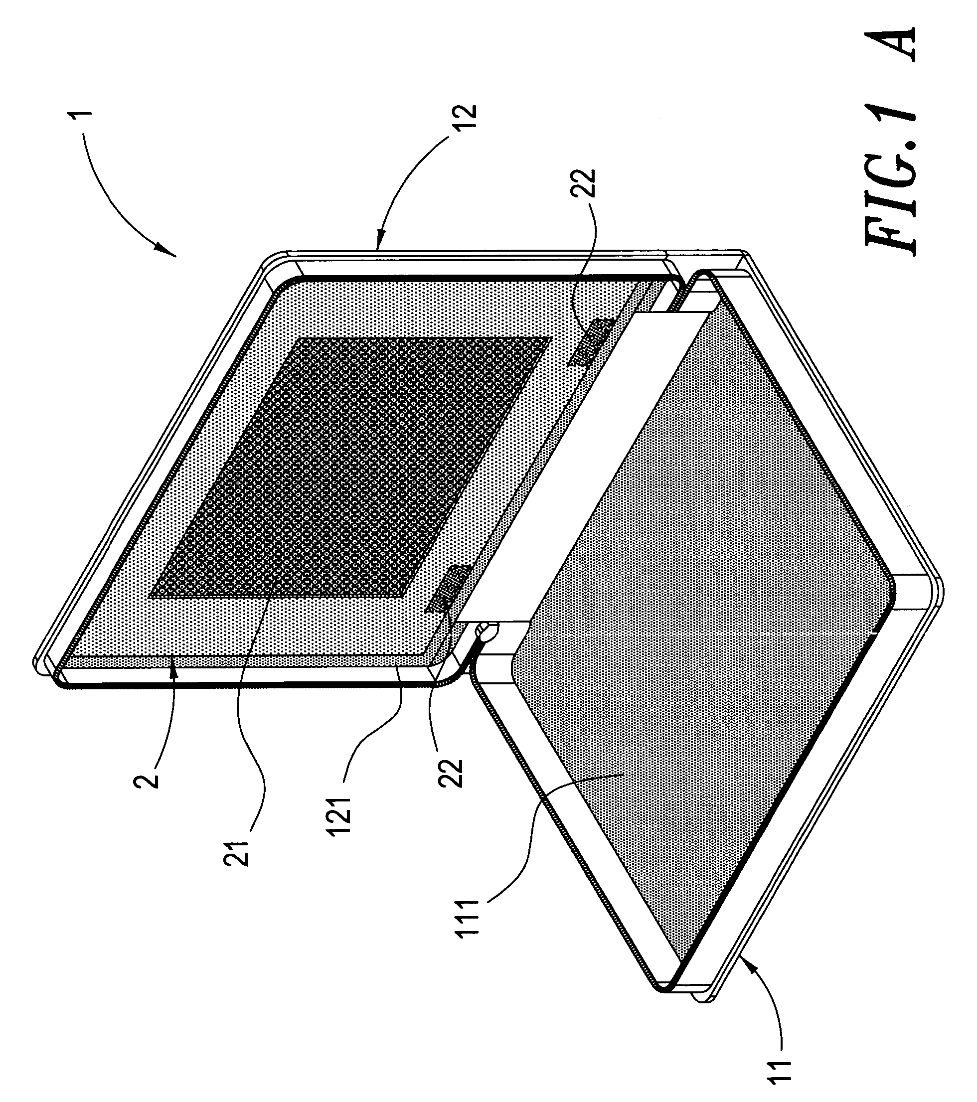
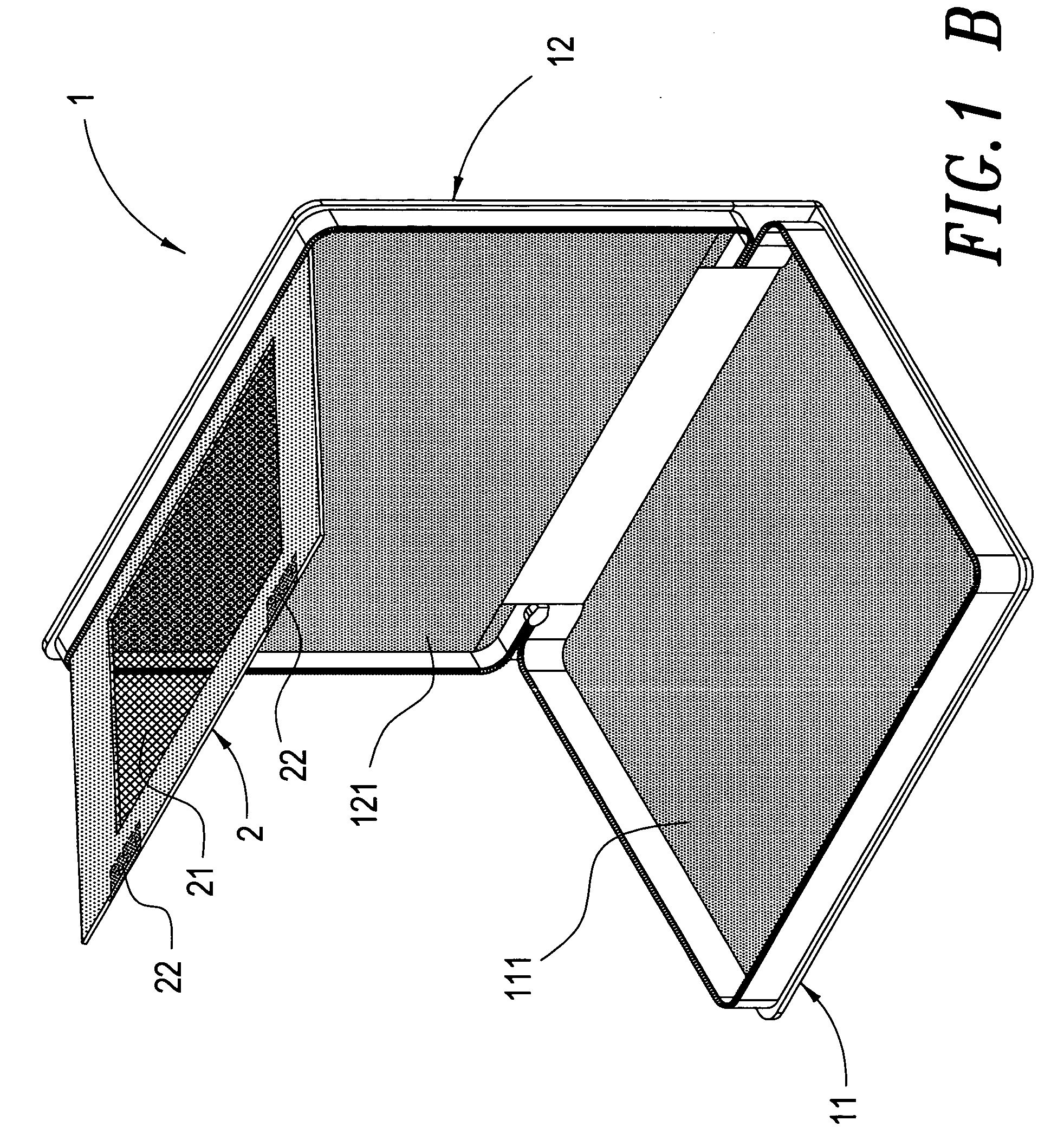
[0015] Referring to FIGS. 1A, 1B, 1C, FIG. 2, and FIG. 3, a protective sleeve structure for a portable electric product according to the present invention mainly comprises:

[0016] A protective sleeve 1, the protective sleeve 1 can contain an electric product, primarily including a first, second body 11,12, sticking-layers 111,121 are paved on both bottoms of the first body and second body 11,12 respectively, the sticking-layer 111,121 can be flannelette or other weaving capable of being stuck by a Velcro, and the first body and second body 11,12 are associated by a zipper using to control the opening and closing of the protective sleeve 1.

[0017] A support-plate 2, a permeable-net 21 installed on the support-plate 2, at least one or more Velcro 22 sewn on the bottom end of the support-plate 2 and the Velcro 22 extends to the back of the bottom end of the support-plate 2; the top end of the support-plate 2 links with the top end of the second body 12 to enable the pivotal-lift featur...


PUM


Abstract

A protective sleeve structure for a portable electric product mainly comprises a protective sleeve. The protective sleeve includes a first body and a second body. A sticking-layer is paved on each bottom surface of the first body and the second body, and a zipper is sewn on the both rims of the first body and the second body so the protective sleeve can be opened and closed by the zipper. The top end of support-plate links with the top end of the second body, and the bottom portion of the support-plate is sewn on at least one or more Velcro. When the user does not want to operate the electric product, the Velcro of the support-plate sticks with the sticking-layer of the second body thus the support-plate is laid on the bottom surface of the second body flatly not to affect the placement of the electric product, thus the user can place the electric product in the protective sleeve as a carryon. When the user does want to operate the electric product, the Velcro on the bottom end of the support-plate sticks with the sticking-layer of the bottom surface of the first body 11 to have the support-plate being inclined so the electric product can be leaned on the support-plate. Hence the user can operate the electric product anytime and anywhere.

Description

BACKGROUND OF THE INVENTION [0001] 1. Field of the Invention [0002] This invention relates to a protective sleeve structure for a portable electric product, particularly to a protective sleeve structure for a portable electric product capable of air permeability and heat diffusivity by using a way to link the support-plate with the protective sleeve, which facilitates an electric product, contained in the protective sleeve, can be operated conveniently. [0003] 2. Description of the Prior Art [0004] In general, a conventional leather sleeve for a portable electric product is used for merely containing the electric product for personal carrying. Contained in the conventional sleeve, the electric product cannot be operated, or the heat generated from the running product cannot be diffused smoothly as the sleeve coating the electric product even the product can be operated. Operating under high temperature, it is possible that the electric product may have a breakdown or its components ...

Claims


Application Information

Patent Timeline
IPC IPC(8): A45C13/02G06F1/16H05K7/02
CPCA45C13/02A45C2011/003G06F1/1628A45C2013/025
Inventor JAO, HAI-PING
Owner APLUX COMM
Why Eureka
Try Eureka