Double-row angular-contact antifriction bearing

a technology of angular contact and bearing, which is applied in the direction of bearings, roller bearings, shafts, etc., can solve the problems of increased wear of the bearing right up to the failure of the bearing, and the inability to achieve the desired play between the rolling elements of the inner bearing ring

Active Publication Date: 2005-10-20
FAG KUGELGISCHER GEORG SCHAFER
View PDF6 Cites 18 Cited by
  • Summary
  • Abstract
  • Description
  • Claims
  • Application Information

AI Technical Summary

Benefits of technology

This patent describes a new type of bearing called a double-row Angular-Contact Antifriction Bearing (ACB) that solves problems associated with traditional bearings. It includes a special distance ring that connects the different parts of the bearing together, allowing them to fit tightly without any movement during use. This also ensures that each component is always under the correct level of stress, reducing wear and tear. Overall, this new design improves performance and reliability compared to other types of bearings.

Problems solved by technology

The technical problem addressed in this patent is how to achieve a precise level of axial pression (the pressure applied along the direction of movement) within the bearings used in various applications, particularly when there are varying levels of precision in the dimensions of the components involved. Current methods involve difficult procedures and often lead to incomplete pression, resulting in poor performance and potential damage to the bearings.

Method used


Image

  • Double-row angular-contact antifriction bearing
  • Double-row angular-contact antifriction bearing

Examples


Embodiment Construction

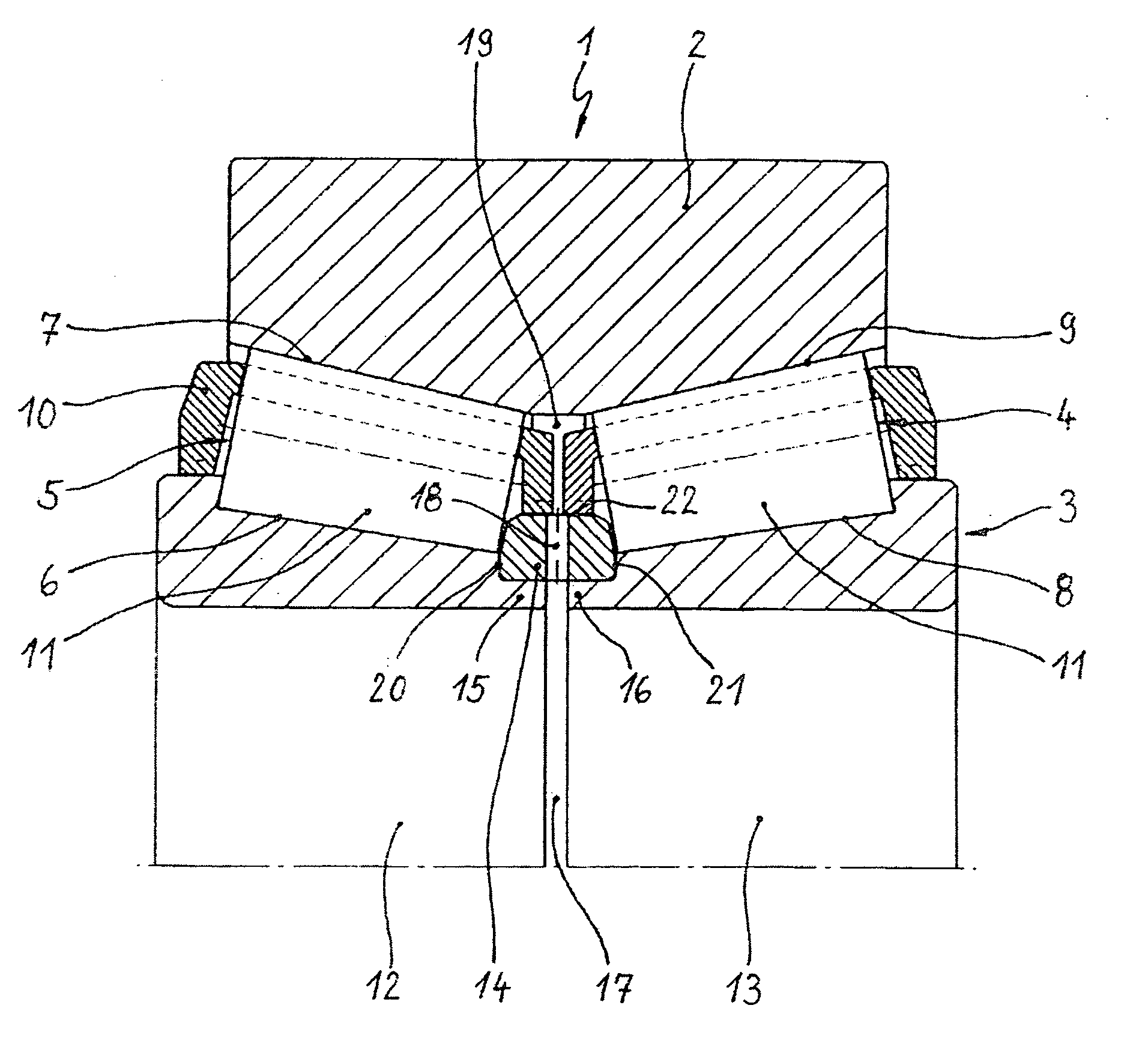
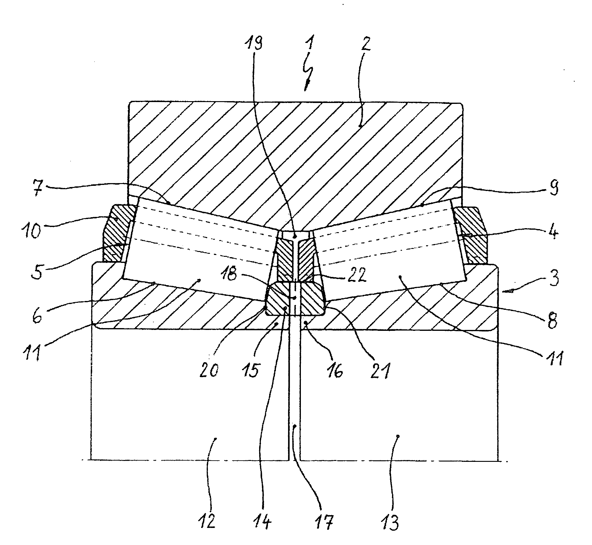
[0008] According to the invention, this object is achieved in the case of a double-row angular-contact antifriction bearing by the angular-contact antifriction bearing being designed as a construction unit which is preassembled in a ready-to-fit manner and has defined axial prestress between the rolling elements and in which the distance ring between the individual rings of the axially split inner bearing ring is at the same time designed as the connecting element of the individual rings.

[0009] In an exemplary embodiment, the angular-contact antifriction bearing according to the invention is preferably designed as a double-row tapered roller bearing in O arrangement which has a one-piece outer bearing ring and an inner bearing ring axially split into two individual rings. In this case, the design of this tapered roller bearing as a construction unit, which is preassembled in a ready-to-fit manner and has defined axial prestress between the rolling elements, is effected in such a wa...


PUM


Abstract

A double-row angular-contact antifriction bearing including an outer bearing ring, and an inner bearing ring and rolling elements between the bearing rings in two rows next to one another on raceways of the bearing rings. A bearing cage for the rolling elements. The inner bearing ring is axially split and is of two individual rings which are connected and between which a distance ring defines axial prestress between the rolling elements of the both rows. The distance ring between the individual rings of the axially split inner ring is a connecting element of the individual rings.

Description


Claims


Application Information

Patent Timeline
Owner FAG KUGELGISCHER GEORG SCHAFER
Why Eureka
Try Eureka