Location loading material testing machine

A material testing machine and loading system technology, applied in the direction of analyzing materials, applying stable tension/pressure to test material strength, measuring devices, etc., can solve the problems of large floor area, expensive equipment use and maintenance costs, etc., to achieve occupancy The effect of small space, simple and clear equipment principle and simple structure

Inactive Publication Date: 2010-11-10
JIANGSU UNIV
View PDF8 Cites 44 Cited by
  • Summary
  • Abstract
  • Description
  • Claims
  • Application Information

AI Technical Summary

Problems solved by technology

[0006] The purpose of the present invention is to provide a multi-functional material testing machine through positioning and loading, which solves the shortcomings of previous equipment such as expensive use and maintenance costs and large

Method used


Image

  • Location loading material testing machine
  • Location loading material testing machine
  • Location loading material testing machine

Examples


Embodiment Construction

[0022] specific implementation plan

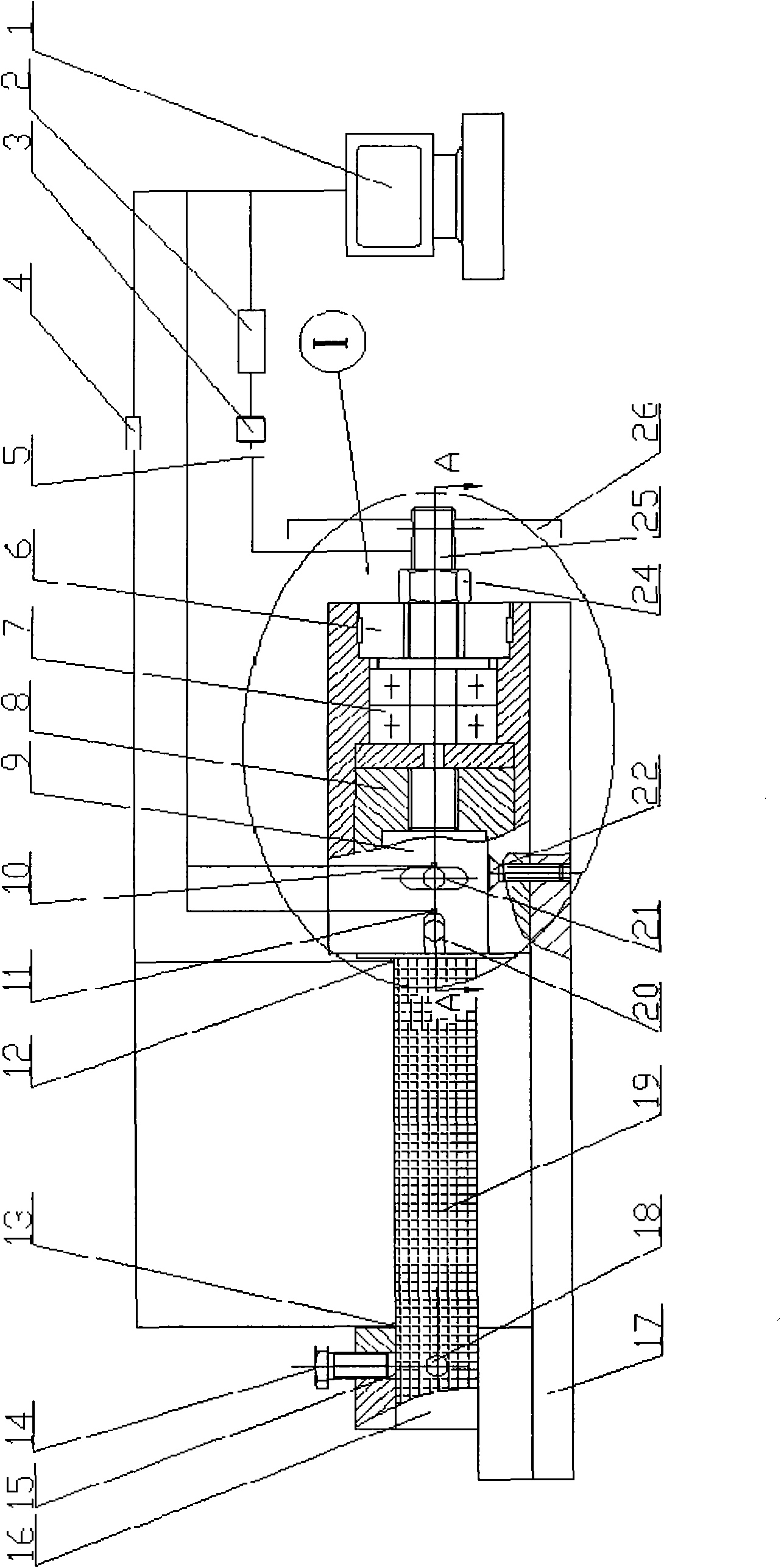
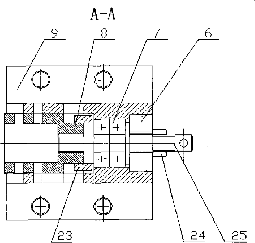
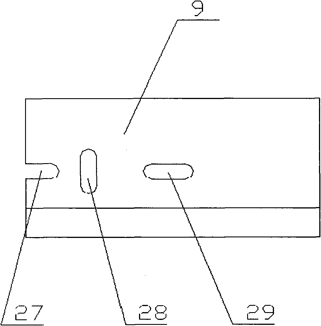
[0023] Said invention consists of figure 1 The overall structure diagram of the material testing machine, figure 2 Positioning and loading system (section top view), image 3 Locate the loading base (appearance front view), Figure 4 Front view of the flanged shaft and Figure 5 Flange shaft side view composition. The loading method is divided into automatic control loading and manual control loading.

[0024] The specific function realization mode of the patented material testing machine of the present invention is as follows:

[0025] 1. Control system: during automatic loading, input the required realization parameter value on the corresponding program interface of the industrial computer 1, and then the software sends a control signal to the motion control card 2, and the motion control card 2 drives the stepping motor after processing the control information 3 rotates, the stepper motor 3 drives the flange shaft 25 to rotate th...


PUM


Abstract

The invention relates to a location loading material testing machine which belongs to the technical field of material test. The location loading material testing machine is characterized in a location loading system; a support stand and a loading support part of the location loading system are respectively positioned at both ends of a fixing base; the loading support part comprises a location loading stand, a flange shaft, an overrunning clutch, a rolling bearing, a groove-shaped nut and two sliding blocks; three guide grooves are arranged on the location loading stand; the sliding blocks are respectively positioned in two keyways of the right external diameter of the groove-shaped nut; the overrunning clutch and the rolling bearing are fixed in the location loading stand in parallel; one end of the flange shaft is fixed by a hexagon nut through threads, and the other end is connected with the groove-shaped nut by threads; the left side of the groove-shaped nut is provided with a groove-shaped cavity; two through holes which are distributed left and right are radially arranged in the groove-shaped cavity; and the positions of the two through holes correspond to the first guide groove and the second guide groove on a loading support stand. The invention can realize a series of tension and compression tests and torsion tests by applying the guide grooves in the horizontal direction and the vertical direction of a location tension-compression-torsion loading stand.

Description

technical field [0001] The invention belongs to the technical field of metal material testing, and in particular provides a positioning loading material testing machine with simple structure and complete functions. Background technique [0002] With the development of industrial technology, the requirements for various mechanical properties of materials are getting higher and higher, which requires accurate testing of materials. It also improves the performance of the application to the material testing machine. Simple structure, complete functions, strong field applicability and high detection reliability have become new requirements for material testing machines. [0003] At present, the existing technology has the State Intellectual Property Office authorization announcement number: CN200982938Y, patent name: a spring tension and compression testing machine; authorization announcement number: CN200986512Y, patent name: spring tension and compression testing machine; and ...

Claims


Application Information

Patent Timeline
IPC IPC(8): G01N3/08G01N3/26
Inventor 冯爱新聂贵锋徐传超卞兆生孙淮阳曹宇鹏王俊伟周鹏程
Owner JIANGSU UNIV
Why Eureka
Try Eureka