
Multi-cylinder hydraulic antifriction bearing taper crusher

A cone crusher and rolling bearing technology, applied in the field of mining machinery and equipment, can solve the problems of poor assembly process of iron passing and cavity cleaning devices, increased machine maintenance costs and downtime, increased machine use costs, etc., to improve crushing efficiency and output , simple structure, and the effect of reducing the cost of equipment use

Active Publication Date: 2012-02-22
ZHEJIANG ZHEKUANG HEAVY IND CO LTD
View PDF7 Cites 44 Cited by
  • Summary
  • Abstract
  • Description
  • Claims
  • Application Information

AI Technical Summary

Problems solved by technology

The force generated by the moving cone and the material entering the crushing chamber will act on the copper sleeve, and there is sliding friction between the copper sleeve and the moving cone, so the copper sleeve is easily damaged, which increases the maintenance cost and downtime of the machine, resulting in The cost of using the machine increases
[0006] 2. In the spring-type iron-passing and cavity-cleaning device, the spring is prone to stress relaxation; and the use of springs makes the assembly process of the iron-passing and cavity-cleaning device very poor
According to the existing experience, the movable cone without anti-rotation device can not only rotate clockwise, but also counterclockwise in the crushing chamber. The counterclockwise rotation of the movable cone will cause the material to slip in the crushing chamber, so Cause large ore discharge particles, lower production efficiency, and large energy waste

Method used


Image

  • Multi-cylinder hydraulic antifriction bearing taper crusher
  • Multi-cylinder hydraulic antifriction bearing taper crusher
  • Multi-cylinder hydraulic antifriction bearing taper crusher

Examples


Embodiment Construction

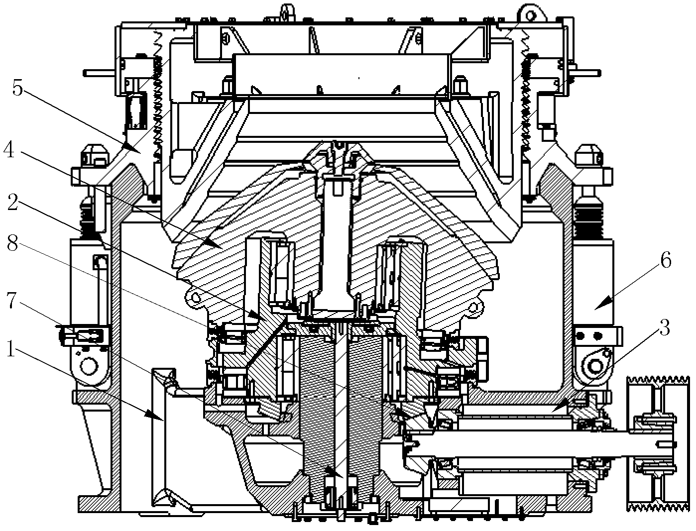
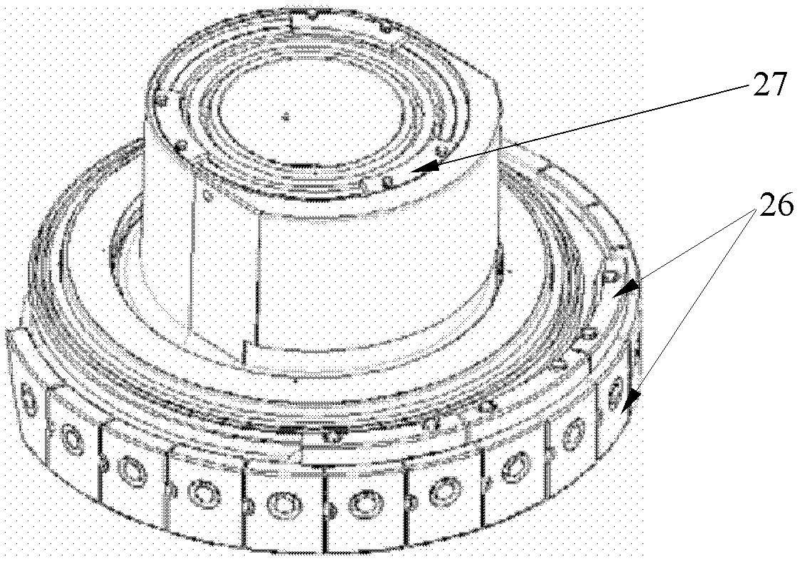
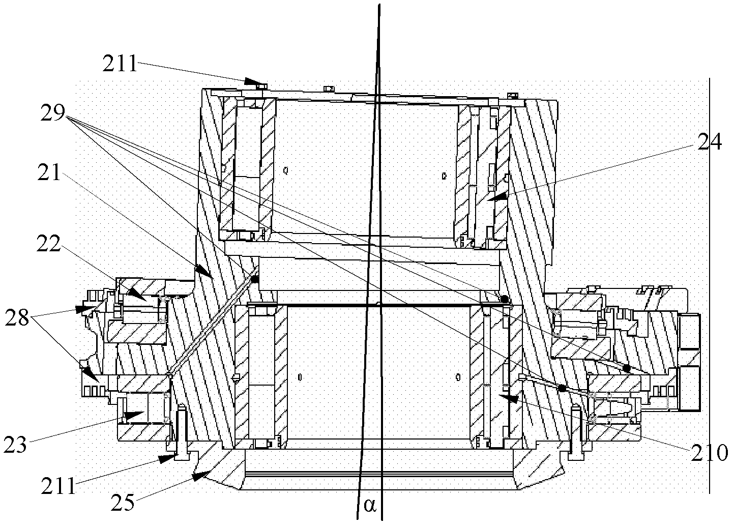
[0030] Such as figure 1 As shown, the multi-cylinder hydraulic rolling bearing cone crusher includes a lower frame 1, an eccentric shaft sleeve mechanism 2, a transmission group 3, a moving cone 4, an upper frame group 5, and an iron and cavity cleaning device 6. The upper frame Group 5 is set above the lower frame 1, the transmission group 3 and the eccentric bush mechanism 2 are installed on the lower frame 1, the transmission group 3 is connected with the eccentric bush mechanism 2, and the eccentric bush mechanism 2 is equipped with a moving cone 4. The lower frame 1 and the upper frame group 5 are directly equipped with an iron passing and cavity cleaning device 6, the eccentric bushing mechanism 2 adopts a rolling bearing type eccentric bushing mechanism 2, and the iron passing and cavity cleaning device 6 adopts an overflow The flow valve type iron passing and cavity clearing device 6, the bottom of the moving cone 4 is also connected with the moving cone anti-rotation ...


PUM


Abstract

The invention discloses a multi-cylinder hydraulic antifriction bearing taper crusher, which comprises a lower machine frame, an eccentric sleeve mechanism, a transmission set, a movable tapper, an upper machine frame set and an iron passing and cavity clearing device. The upper machine frame set is arranged above the lower machine frame, the transmission set and the eccentric sleeve mechanism are both installed on the lower machine frame, the transmission set is connected with the eccentric sleeve mechanism where the movable tapper is arranged, the iron passing and cavity clearing device is directly installed on the lower machine frame and the upper machine frame set, the eccentric sleeve mechanism adopts an antifriction bearing type eccentric sleeve mechanism, the iron passing and cavity clearing device adopts a relief valve type iron passing and cavity clearing device, and a movable tapper body rotating-proof device is connected to the bottom of the movable tapper. The multi-cylinder hydraulic antifriction bearing taper crusher improves crushing efficiency and output of the taper crusher, and prolongs service life of a machine, reduces using cost of equipment. The iron passing and cavity clearing device can not only bear higher working pressure of a system, but also be safe and reliable, convenient to assemble and capable of controlling a tapper body to rotate according to certain direction, thereby improving production efficiency and saving energy.

Description

【Technical field】 [0001] The invention relates to mining machinery equipment, in particular to an improvement on the structure of a multi-cylinder hydraulic rolling cone crusher. 【Background technique】 [0002] Multi-cylinder hydraulic rolling cone crusher is a commonly used mining machinery and equipment. [0003] The structure of the multi-cylinder hydraulic rolling cone crusher in the prior art includes: a lower frame, an upper frame, an eccentric shaft sleeve, a moving cone group, a transmission group, a spring group, a copper seat, a copper sleeve and a gear pair. The eccentric shaft sleeve is connected with the lower frame through the copper sleeve, the moving cone is set on the copper seat, and the transmission group transmits the power to the eccentric shaft sleeve through the gear pair, so as to drive the moving cone to rotate and swing to realize the extrusion and crushing work. [0004] The multi-cylinder hydraulic rolling cone crusher with this structure has the...

Claims


Application Information

Patent Timeline
Patent Type & Authority Applications(China)
IPC IPC(8): B02C2/04
Inventor 赵孟军陈连方陈立波李国强
Owner ZHEJIANG ZHEKUANG HEAVY IND CO LTD
Learn More