Radio frequency identification of a connector by a patch panel or other similar structure

a technology of radio frequency identification and connector, which is applied in the direction of using reradiation, indirect connection of subscribers, transmission, etc., can solve the problems of fiber optic cable being removed inadvertently from the host device, fiber optic cable no longer transmitting light energy to the host device, and the job of workers becoming very burdensome and time-consuming, etc., to facilitate the identification of a specific connector

Inactive Publication Date: 2005-10-20
STRATOS INT
View PDF22 Cites 127 Cited by
  • Summary
  • Abstract
  • Description
  • Claims
  • Application Information

AI Technical Summary

Benefits of technology

[0009] It is an object of the invention to provide a device which facilitates the identification of a specific connector or cable relative to a specific location on a panel.

Problems solved by technology

Experience has shown that a fiber optic cable can be inadvertently detached from the host device, or that the optical fiber within the fiber optic cable breaks and the fiber optic cable no longer transmits light energy to the host device.
When two or more fiber optic cables are malfunctioning, the worker's job becomes very burdensome and time consuming since there are hundreds of fiber optic cables to examine.
Furthermore, a device or person is not receiving information conveyed by the malfunctioning fiber optic cable.

Method used


Image

  • Radio frequency identification of a connector by a patch panel or other similar structure
  • Radio frequency identification of a connector by a patch panel or other similar structure
  • Radio frequency identification of a connector by a patch panel or other similar structure

Examples


Embodiment Construction

[0031] Referring now to the drawings, wherein like reference numerals designate identical or corresponding parts throughout the several views, and more particularly to FIGS. 6-15 thereof, embodiments of the present invention are displayed therein.

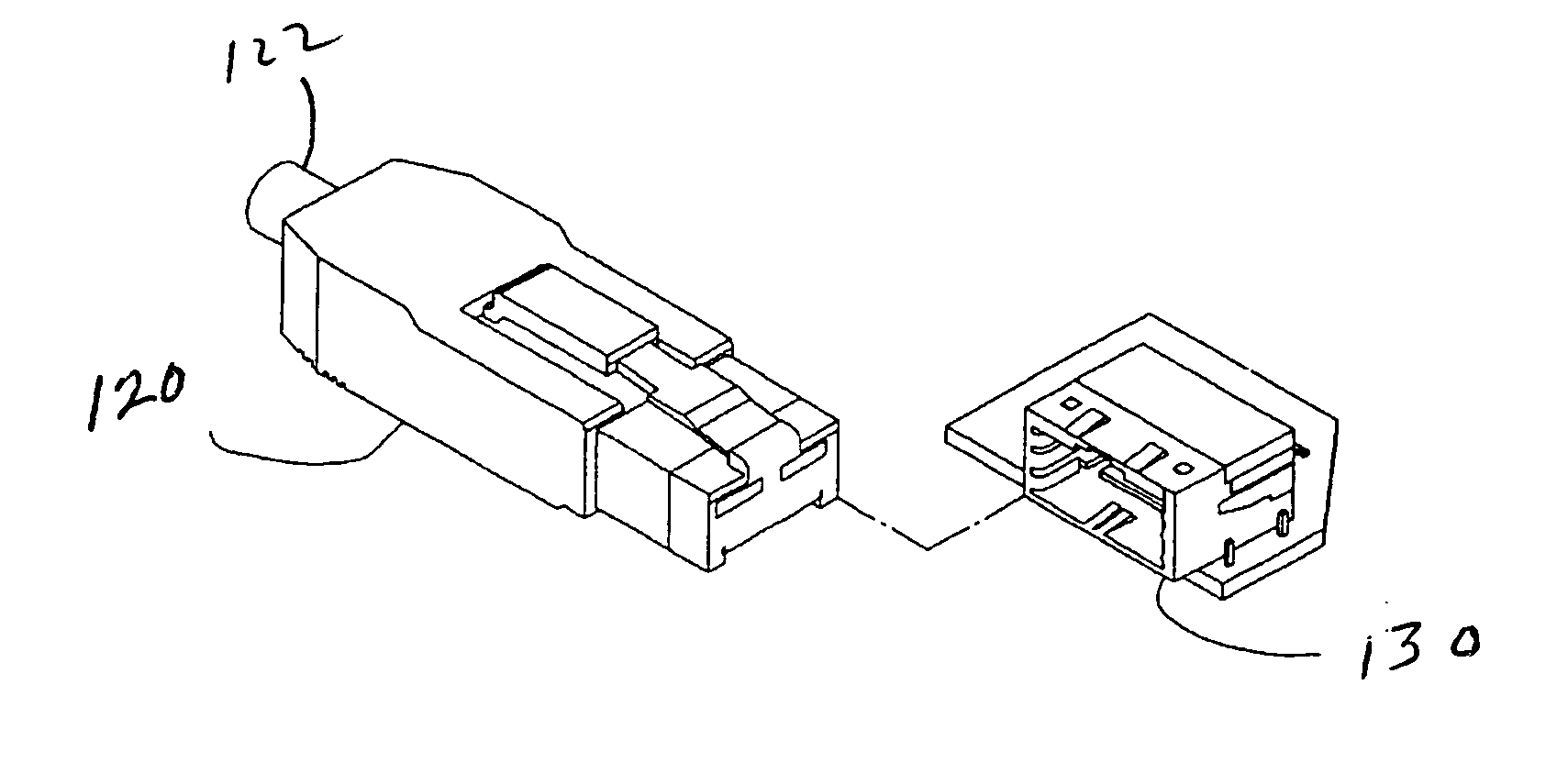
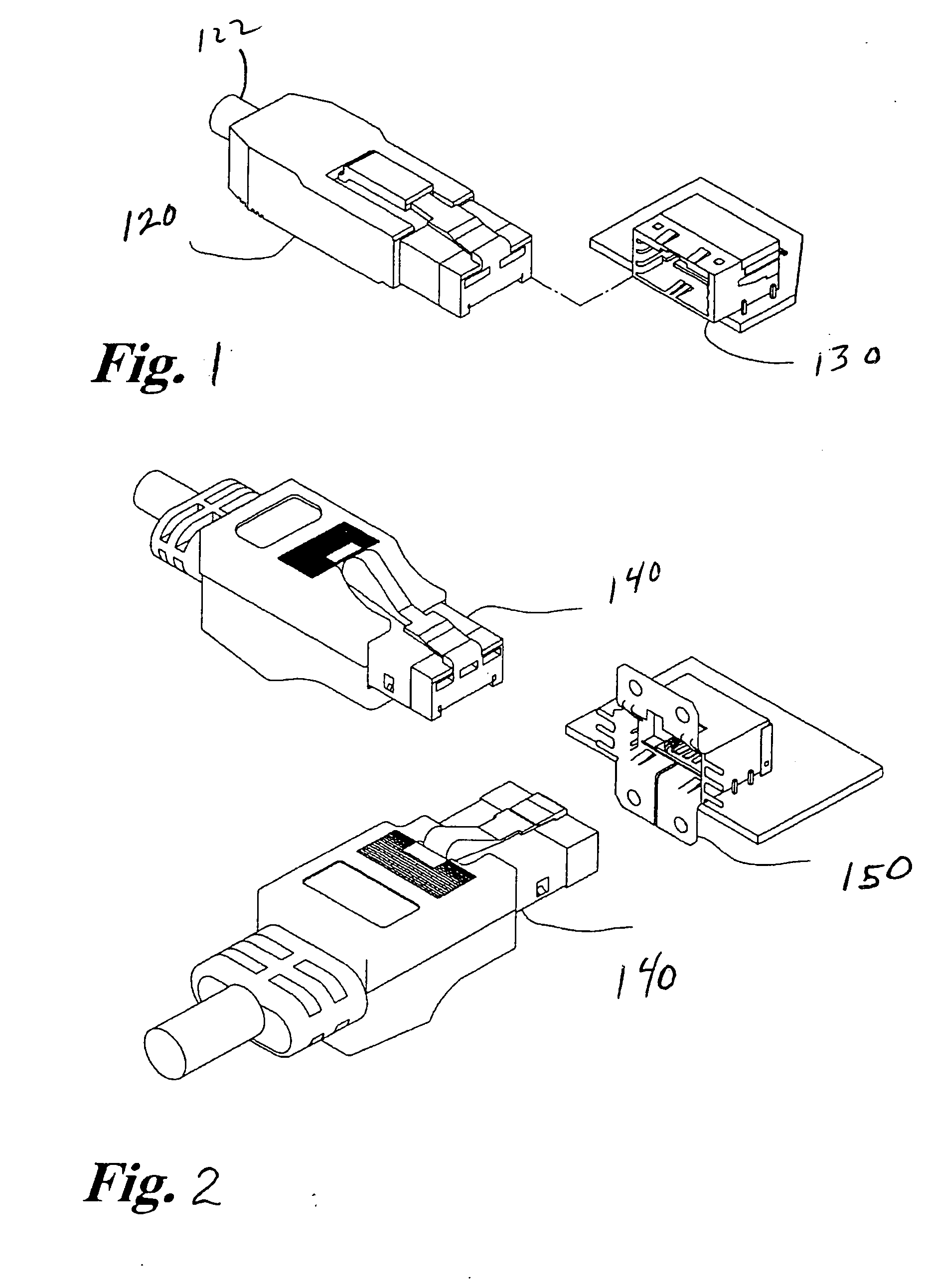
[0032]FIG. 6 is a perspective view of a fiber optic cable 30 having a fiber optic connector 10. The fiber optic connector 10 includes a release lever 40. Attached to the fiber optic connector 10 is a strain relief boot 20. Also attached to, or mounted on or in, the fiber optic connector 10 is a transponder 70. The transponder 70 can be affixed to the fiber optic connector 10 with an adhesive material or a clip (not shown). The clip physically squeezes or clamps the transponder 70 to the fiber optic connector 10. Alternatively, the transponder 70 can be insert molded into the body of the fiber optic connector 10. Furthermore, the transponder 70 can be attached to fiber optic connectors which are already in-service.

[0033]FIG. 7 is a perspec...


PUM


Abstract

The device includes a fiber optic cable, a transponder, an antenna, and a transceiver. The transponder is attached to a fiber optic connector of the fiber optic cable. The transceiver is electrically connected to the antenna, the transceiver is able to activate the transponder thus enabling the transceiver to read the information deposited with the transponder. Information deposited with the transponder can include information related to the length of the fiber optic cable, information related to the industrial standard to which the fiber optic connector conforms, information related to the predetermined optical fiber grade of the optical fiber of the fiber optic cable, information related to the specific purchase date of the fiber optic cable, or information related to the warranty of the fiber optic cable.

Description

BACKGROUND OF THE INVENTION [0001] 1. Field of the Invention [0002] The present invention pertains to radio frequency identification devices. The invention more particularly concerns the radio frequency identification of a connector by a patch panel. [0003] 2. Discussion of the Background [0004] Radio frequency identification devices (RFID) are known in the art. Typically, radio frequency identification systems incorporate an antenna or coil, a transceiver (with decoder), and a transponder (RF tag). Often times the antenna and the transceiver are packaged together so as to form a reader or interrogator. The transponder includes a transponder antenna and an integrated circuit chip attached to the transponder antenna. The antenna or coil emits a radio wave which induces an electrical current in the antenna of the transponder. The electrical current then activates the integrated circuit chip of the transponder. The integrated circuit chip can then transmit information through the anten...

Claims


Application Information

Patent Timeline
Patent Type & Authority Applications(United States)
IPC IPC(8): G01S13/08G02B6/36G02B6/38G06K19/06G08B21/00H04B7/00H04B10/00H04B10/12H04Q5/22
CPCG02B6/3807G02B6/381H04B10/25758G02B6/3895G02B6/385
Inventor DURRANT, RICHARD C. E.FITZGIBBON, MAURICE
Owner STRATOS INT
Why Eureka
Try Eureka