Test connector with metallic stiffener

a technology of metallic stiffener and test connector, which is applied in the direction of coupling device connection, measurement instrument housing, instruments, etc., can solve the problems of terminal damage, terminal damage, and terminal damage, so as to reduce the risk of lead damag

Inactive Publication Date: 2005-10-20
HON HAI PRECISION IND CO LTD
View PDF7 Cites 9 Cited by
  • Summary
  • Abstract
  • Description
  • Claims
  • Application Information

AI Technical Summary

Benefits of technology

[0011] An object of the present invention is to provide a test connector for electrically testing an electronic package such as an LGA chip, whereby the test connector is configured to minimize the risk of damage to leads of an associated electronic package.

Problems solved by technology

The leads and the terminals are thus liable to sustain damage.
Thus, smooth movement of the cover 92 along the base 91 is disrupted, which can result in damage to the leads of the IC package and the terminals of the base 91.
When this happens, the leads of the IC package enter the terminals of the base 91 with great speed and force, and the leads and the terminals are liable to sustain damage.

Method used


Image

  • Test connector with metallic stiffener
  • Test connector with metallic stiffener
  • Test connector with metallic stiffener

Examples


Embodiment Construction

[0023] Reference will now be made to the drawings to describe the present invention in detail.

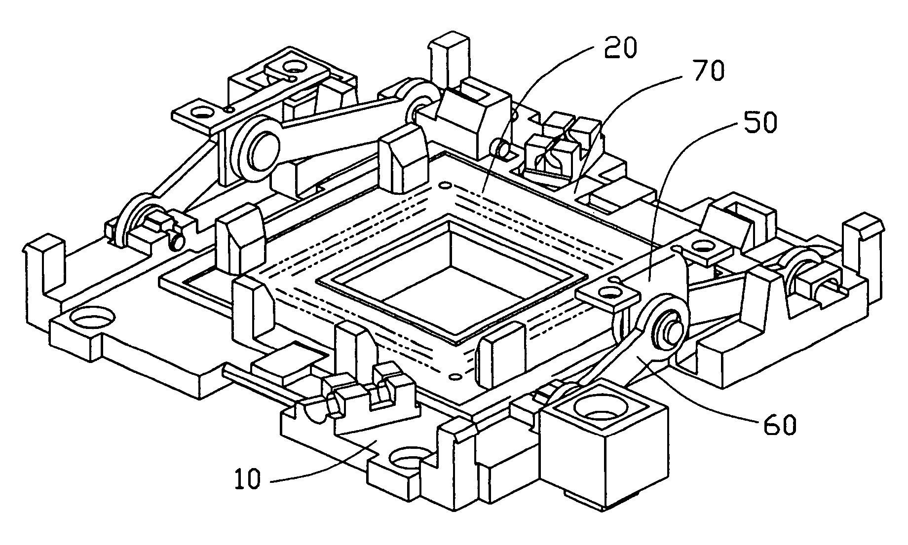
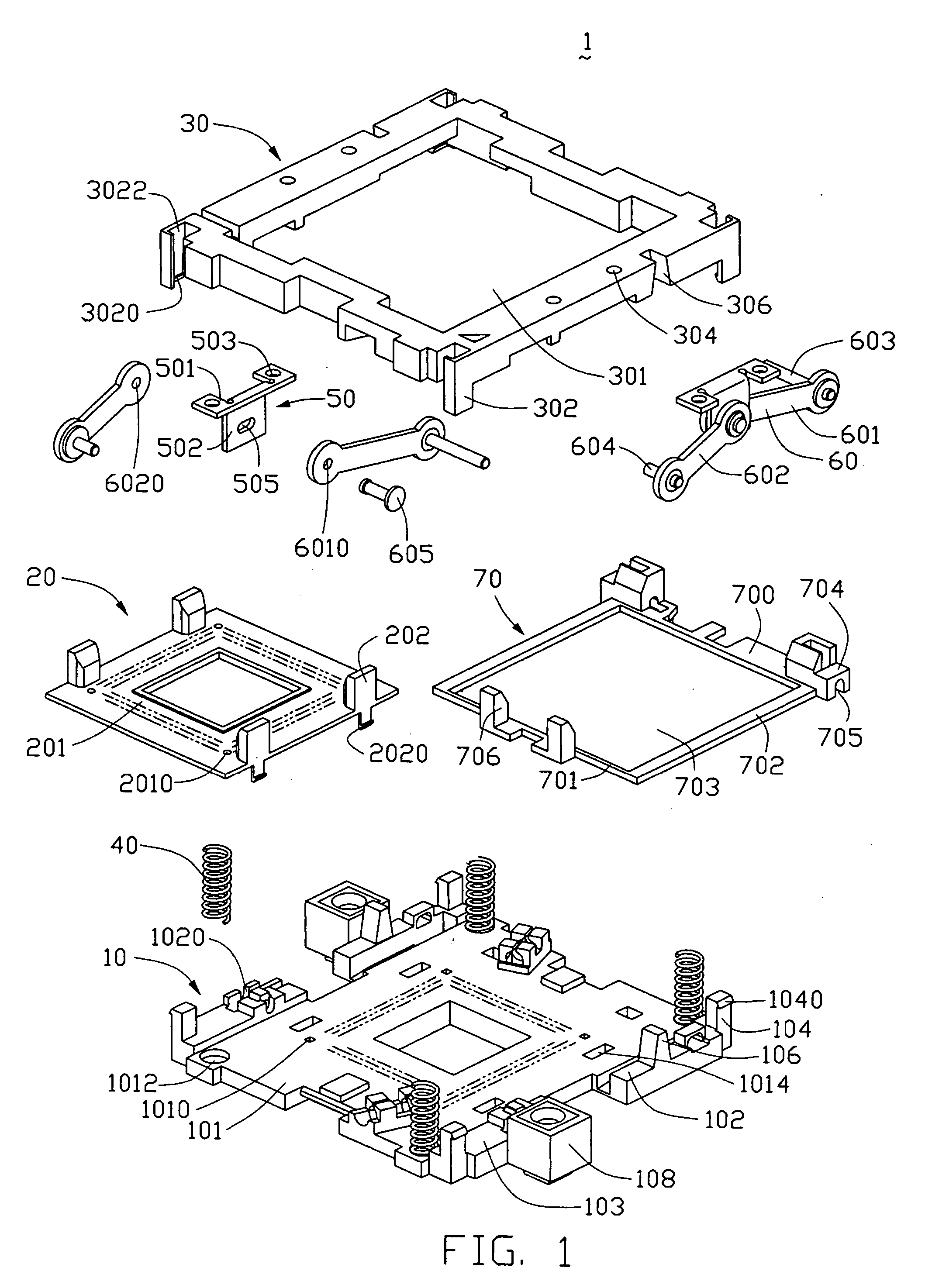
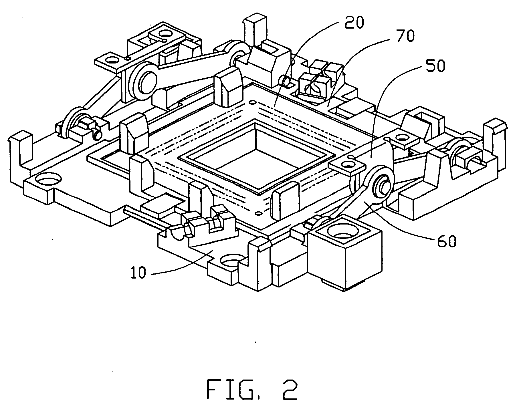
[0024] Referring to FIG. 1, a test connector 1 in accordance with the preferred embodiment of the present invention is adapted for receiving an integrated circuit (IC) package such as a central processing unit (CPU) (not shown) in order to test the CPU. The test connector 1 comprises a generally rectangular base 10, with a plurality of terminals (not shown) received therein, fixed on a circuit substrate such as a printed circuit board (PCB) (not shown), a generally rectangular cover 20 slidably mounted on the base 10, a metallic stiffener 70 engaged with the cover 20, a lid 30, four coil springs 40 received between the lid 30 and base 10, a pair of inserting plates 50, and a pair of operating members 60 for actuating horizontal movement of the frame 70 and the cover 20.

[0025] The base 10 includes a rectangular main portion 101, a pair of first side portions 102 at opposite lateral sides o...


PUM


Abstract

A test connector (1) includes a base (10), a cover (20), a metallic stiffener (70), two operating members (60), and a lid (30). An opening (703) is defined in the stiffener for receiving the cover therein. Two spaced projections (704) are formed on one end of the stiffener. Two receiving grooves (705) are defined in bottoms of the projections respectively. Each operating member comprises a first operating lever (601) engaged with the receiving grooves via a first shaft (603), and a second operating lever (602) engaged with the base. The lid is engaged with the operating members for pivotably moving the first and second operating levers so that the operating members actuate the stiffener and the cover to move. When the cover moves to make the terminals connect a CPU during applying an unduly force on the lid, the metallic stiffener can protect the plastic cover from damage.

Description

BACKGROUND OF THE INVENTION [0001] 1. Field of the Invention [0002] The present invention relates to an electrical connector such as a test socket used for testing of integrated circuit (IC) packages, and particularly to an electrical connector with a metallic stiffener that minimizes the risk of accidental damage to a cover of the connector. [0003] 2. Description of the Prior Art [0004] Test connectors are widely used for receiving and testing of IC packages such as land grid array (LGA) chips. A conventional test connector includes a main body, and a plurality of operating levers for actuating lateral movement of the movable plate along the main body. The movable plate is movable between a released state in which the IC package is attached thereon but electrically disengaged terminals in the main body, and a contacting state in which the IC package is electrically engaged with the terminals. U.S. Pat. Nos. 5,186,642 and 5,702,255 disclose this kind of test connector. [0005]FIG. 6 ...

Claims


Application Information

Patent Timeline
Patent Type & Authority Applications(United States)
IPC IPC(8): G01R1/04H01R12/00H01R13/193
CPCG01R1/0433
Inventor GATTUSO, ANDREW D.HSU, HSIU-YUAN
Owner HON HAI PRECISION IND CO LTD
Why Eureka
Try Eureka