Marker detection method and apparatus, and position and orientation estimation method

a marker and detection method technology, applied in the field of marker detection methods and apparatus, can solve the problems of affecting the accuracy of the final position and orientation calculation precision of the image sensing device, and affecting the accuracy of the final position and orientation calculation. the effect of detecting the feature points of the marker that are used to detect the error

Inactive Publication Date: 2005-10-20
CANON KK
View PDF8 Cites 106 Cited by
  • Summary
  • Abstract
  • Description
  • Claims
  • Application Information

AI Technical Summary

Benefits of technology

[0021] With the above arrangement, since a marker which may suffer partial occlusion is determined on the basis of a color included in an adjacent region of the marker region, use of the erron...

Problems solved by technology

For example, if a plurality of regions recognized as markers from a captured image include at least one erroneously detected one, the finally obtained precision of the position and orientation impairs considerably.
Since the partially-occluded marker is detected as a region having a shape different from a region to be detected, the barycentric position and the coordinates of vertices are erroneously recognized or calculated, thus deteriorat...

Method used


Image

  • Marker detection method and apparatus, and position and orientation estimation method
  • Marker detection method and apparatus, and position and orientation estimation method
  • Marker detection method and apparatus, and position and orientation estimation method

Examples


first embodiment

[0039] A case will be explained hereinafter wherein a marker detection apparatus according to an embodiment of the present invention is applied to a mixed reality (MR) space presentation system using a video see-through type head-mounted display (HMD).

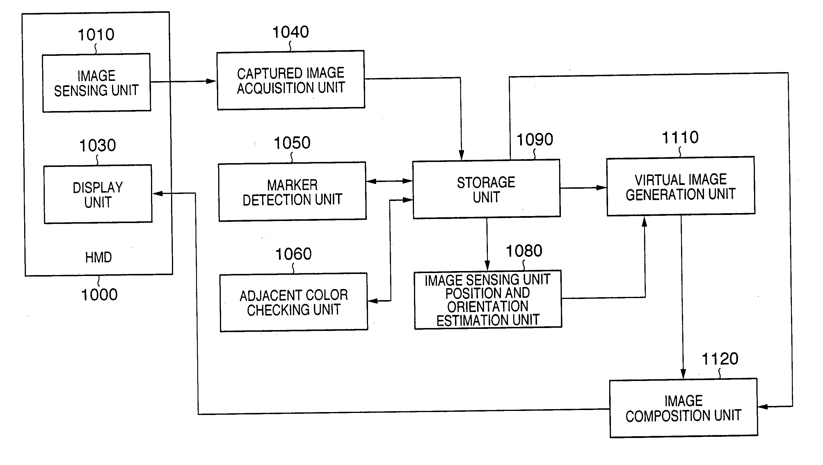
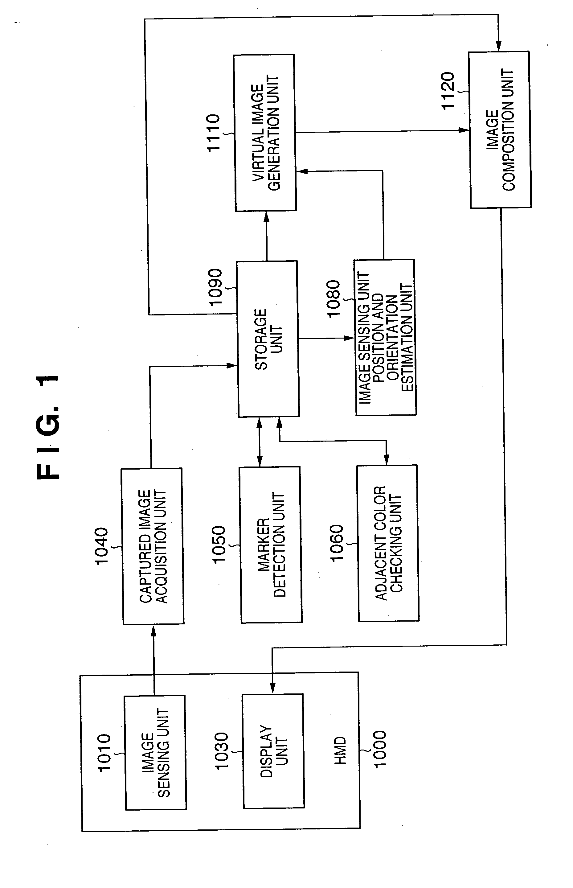
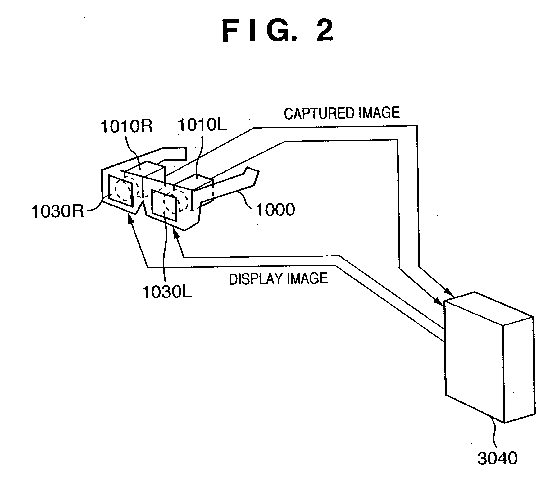
[0040] A marker detection apparatus of this embodiment can precisely detect the position and orientation of an image sensing unit (the term “image sensing unit” indicates a pair of right and left cameras together unless otherwise specified) attached to the video see-through type HMD. As a result, an image on a virtual space rendered by computer graphics or the like can be correctly aligned to a real space image obtained by capturing a real space when they are superimposed and composited, and the user who observes this composite image via the HMD can naturally experience the mixed reality space (to be referred to as MR space hereinafter).

[0041] The MR space presentation system presents an MR space image generated by compositing an ima...

modification 1

[Modification 1]

[0095] In the first embodiment, when the adjacent region of the detected marker includes a specific color, it is determined that the marker has suspicion of partial occlusion, and that marker is deleted from the detected marker list. However, the determination method of erroneous detection due to partial occlusion is not limited to this. A color (surrounding color) of a surrounding region where the marker is set may be acquired when the marker is not occluded, and may be registered in the storage unit 1090. The adjacent color checking unit 1060 checks if the adjacent region of the detected marker includes a color other than the registered surrounding color. If a color other than the surrounding color is detected, that marker may be deleted from the detected marker list.

[0096] The arrangement of the MR space presentation system of this modification is the same as that in the block diagram of FIG. 1. However, the internal process of the adjacent color checking unit 10...

modification 2

[Modification 2]

[0099] In the first embodiment, when the list includes, as the detected marker, the rectangular marker which is determined to have suspicion of partial occlusion, that rectangular marker is deleted from the list. More specifically, all pieces of information (i.e., all four pieces of vertex information) obtained from the detected marker which is determined to have suspicion of partial occlusion are not used. However, even in the partially occluded detected marker, two pieces of information associated with the vertices 5050 and 5060 which are not occluded are correctly detected. This modification is characterized in that vertex information which may not be occluded of the detected marker with suspicion of partial occlusion is not discarded, and is used in calculations of the position and orientation of the image sensing unit position and orientation estimation unit 1080.

[0100] The arrangement of the MR space presentation system of this modification is the same as that...


PUM


Abstract

This invention relates to a mixed reality presentation apparatus for obtaining the position and orientation of an image sensing unit using markers. Whether or not a marker detected in a captured image has suspicion of partial occlusion is determined by checking if a region that neighbors a marker region includes a predetermined color, thus inhibiting information obtained from the marker with suspicion of partial occlusion from being used in position and orientation estimation of the image sensing unit. The precision of the obtained position and orientation can be improved.

Description

FIELD OF THE INVENTION [0001] The present invention relates to a technique for detecting a region (marker) having a predetermined visual feature from an image and, more particularly, to a technique for eliminating an erroneously detected marker. BACKGROUND OF THE INVENTION [0002] A mixed reality (MR) space presentation system presents an MR space image generated by compositing an image on a real space and that on an unreal space (virtual space) via a head-mounted display (HMD), thus allowing the user who wears the HMD to experience the MR space (or MR) (see H. Tamura, H. Yamamoto and A. Katayama: “Mixed reality: Future dreams seen at the border between real and virtual worlds,” Computer Graphics and Applications, vol. 21, no. 6, pp. 64-70, 2001). [0003] In such MR space representation system, as a method of detecting the position and orientation of an image sensing device that captures the real space (or the position and orientation of a real object with respect to the image sensing...

Claims


Application Information

Patent Timeline
IPC IPC(8): A61B5/05G06T1/00G06T5/00G06T7/00H04N5/232
CPCG02B27/017G02B2027/0138G02B2027/014G06T2207/30204G06T7/0018G06T19/006G06T2207/10024G02B2027/0187G06T7/80
Inventor TAKEMOTO, KAZUKISATOH, KIYOHIDE
Owner CANON KK
Why Eureka
Try Eureka