Wall construction method

a construction method and wall technology, applied in the direction of walls, constructions, building material handling, etc., can solve the problems of high implementation cost, limited scope for varying the external appearance of the brick work to suit different architectural styles and personal tastes, and relatively time-consuming types of masonry construction

Inactive Publication Date: 2005-10-27
JAMES HARDIE RES PTY LTD
View PDF99 Cites 20 Cited by
  • Summary
  • Abstract
  • Description
  • Claims
  • Application Information

AI Technical Summary

Benefits of technology

[0023] Another unexpected advantage of the invention is that a layer of back render on the reverse side of the building sheets is not required, although back render may be applied if desired
[0024] Preferably, however, where back-render is not applied to the inside surfaces of the building sheets between the studs, back priming is applied by brush, roller or spray to all exposed surfaces of the fibre cement sheets.
[0025] Preferably, the reinforcing mesh is formed substantially from fibreglass, and is applied over the top of a first levelling coat of render. Ideally, any joins in the fibreglass mesh are formed with a minimum overlap of around 50 millimetres.
[0026] Preferably, the render is a high-build render, formed from an acrylic-modified cementitious material designed to be screeded to a flat level finish when applied externally to a vertical surface. The render is preferably applied to a depth sufficient to eliminate the possibility for sheet “read” in any normal lighting conditions.
[0027] Preferably also, the method includes the further step of applying a selected texture finish to the render in order to achieve the desired aesthetic impression. Most preferably, a high-quality acrylic texture membrane paint is also applied, either to the texture finish, or to the render if a separate texture finish is not used.
[0028] Preferably, a thermal insulation material is installed on the inside of the building sheets, between the studs, and the wall cavity is then preferably closed by means of an internal lining material such as plasterboard. Any suitable installation material may be used including rock wool, glass wool or polyester batts.

Problems solved by technology

This has the advantage of providing the outward appearance of “double brick” construction but at considerably lower cost Nevertheless, even “brick veneer” and similar, types of masonry construction are relatively time-consuming and expensive to implement A further disadvantage with basic brick veneer construction is that there is little scope for varying the external appearance of the brick work to suit different architectural styles and personal tastes.
Typically, however, these systems require special expertise to apply effectively, add further to the time and cost of construction, and can be prone to other problems such as sagging, delamination and environmental degradation.
Depending upon the particular material concerned, however, in most cases these systems are either less durable, less flexible in terms of surface finishes, less well insulated, have lower strength characteristics, or lack the desired appearance of substance and solidity associated with rendered masonry construction.
However, this system was subject to its own disadvantages.
This system also required adjacent sheets to be joined over the tops of the framing studs, which again added to the construction time, and gave rise to significant material wastage in the form of off-cuts.
Other problems that arose with some known render systems used in conjunction with FRC sheeting were the visibility of the joins through the render which allowed the underlying sheets to be “read” in certain lighting conditions, as well as problems of cracking in the render, particularly in the vicinity of the joins.

Method used


Image

  • Wall construction method
  • Wall construction method
  • Wall construction method

Examples


Embodiment Construction

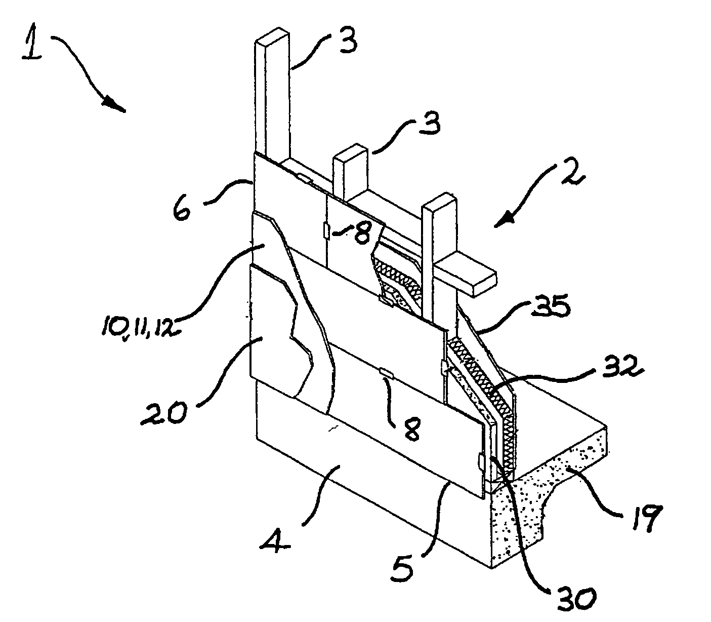
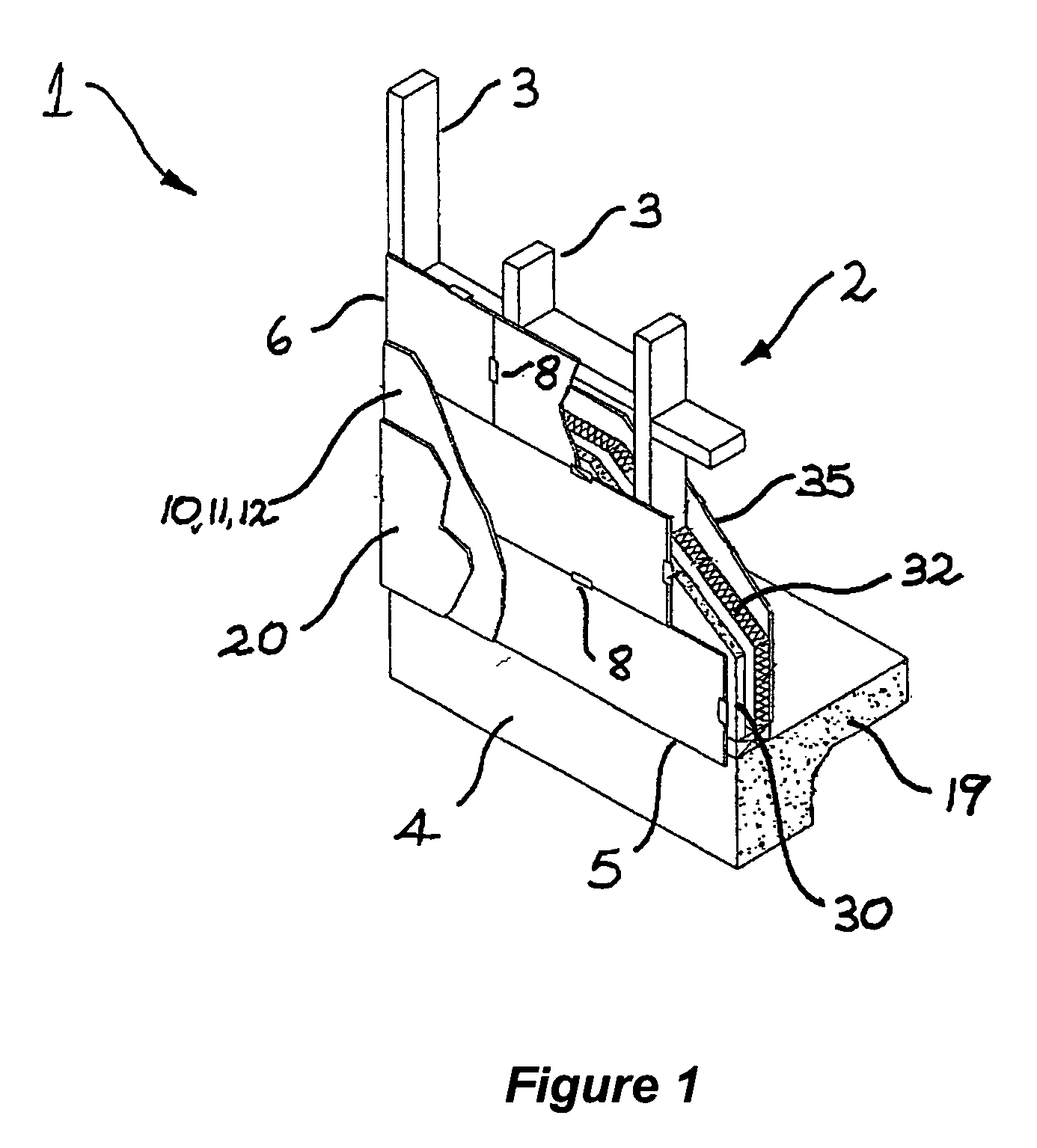
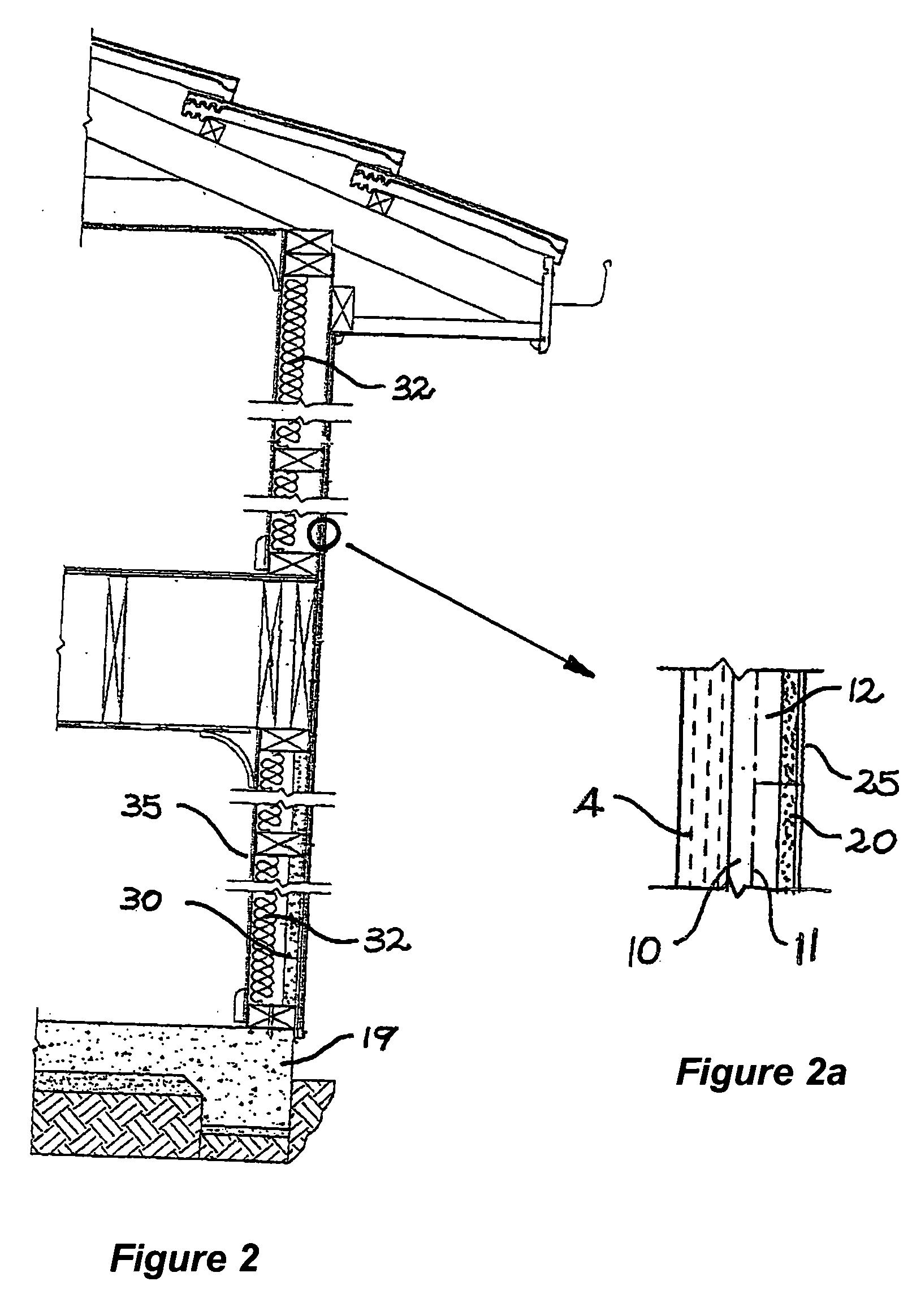
[0044] Referring initially to FIGS. 1 and 2, the invention provides a method for forming a composite wall 1. The first stage in the process involves erecting a structural frame 2 including a series of generally upright studs 3 spaced part at approximately 450 millimetre centres. The frame is preferably formed from timber, but may alternatively be formed from metal or other suitable framing materials.

[0045] The next stage of the process involves positioning a plurality of building or cladding sheets 4 over the frame in a generally horizontal orientation, such that at least a majority of the cladding sheets extend across multiple studs. The sheets are ideally staggered in a brickwork type configuration, which may be regular or irregular, as shown in FIG. 3. FIG. 4 is similar, but shows a typical installation of the sheets around an opening, such as a window or door. In cases such as this, the staggering is preserved as far as possible.

[0046] In the preferred form of the invention, t...


PUM


Abstract

A method for forming a composite wall (1), said method including the steps of: erecting frame (2) including a plurality of generally upright spaced apart studs (3); positioning a plurality of external cladding sheets (4) over the frame in a generally horizontal orientation such that a majority of the cladding sheets extend across two or more of the studs; fastening the sheets (4) to the frame in substantially contiguous abutting relationship to form a generally planar substrate for a wall; and applying a surface render (10, 12) including a reinforcing mesh (11) substantially uniformly over the substrate; thereby to form a structural wall with an external appearance of rendered masonry without the need for supplementary internal rendering, bracing for reinforcement.

Description

FIELD OF THE INVENTION [0001] The present invention relates to a method of housing construction. [0002] The invention has been developed primarily for use in the construction of walk, in domestic dwellings, and will be described primarily with reference to this application. It will be appreciated, however, that the invention is not limited to this particular field of uses, being readily adaptable to the fabrication of floors, ceilings and other generally planar surfaces, not only in residential dwellings but also in commercial and industrial environments. BACKGROUND OF THE INVENTION [0003] Any discussion of the prior art throughout the specification should in no way be considered as an admission that such prior art is widely known or forms part of common general knowledge in the field. [0004] One building construction techniques currently in widespread use for residential dwellings, involves initially fabricating a structural frame, usually from timber or metal and applying an exter...

Claims


Application Information

Patent Timeline
Patent Type & Authority Applications(United States)
IPC IPC(8): E04B1/00E04B2/70
CPCE04B2/707
Inventor LIGGINS, ANDREW
Owner JAMES HARDIE RES PTY LTD
Why Eureka
Try Eureka