Method for extending the range of commercial passive RFID elements

a passive rfid and commercial technology, applied in the field of passive commercial rfid tags, can solve the problems of consuming considerable time to beamform power to one tag, and achieve the effect of efficient search

Active Publication Date: 2022-05-03
CARNEGIE MELLON UNIV
View PDF5 Cites 0 Cited by
  • Summary
  • Abstract
  • Description
  • Claims
  • Application Information

AI Technical Summary

Benefits of technology

[0005]Disclosed herein are systems and methods comprising the present invention which use distributed multiple-input, multiple-output (MIMO) beamforming to increase the communication range of commercial passive RFID tags. The invention synchronizes both transmissions and receptions from multiple, spatially distributed RFID readers to beamform power to RFID tags that may be up to several tens of meters away from any individual reader. In addition, the invention exploits the diversity in location and polarization of readers to further improve range.
[0009]The present invention resolves this dilemma by developing a novel distributed blind beamforming approach to efficiently search through the space of beamforming weights without a response from the tag. At a high level, the invention models the received signal power at each point in space for different beamforming weights applied across reader antennas. Sub-sets of 3D space where RFIDs placed would receive sufficient energy to respond are then identified. Unlike traditional beams of a directional antenna, in the context of distributed MIMO, the regions of space that receive sufficient energy are quite complex and span the entire 3D space as shown in FIG. 1(b). The invention is able to calculate the optimal beamforming weights while minimizing overlap within area of interest using a method analogous to the weighted set-cover problem, a well-known NP-complete problem.
[0010]The invention includes heuristic approximation algorithms to efficiently search the entire space for RFID tags under a limited time budget. A key challenge in ensuring minimal overlap between patterns is the unknown multipath characteristics of the environment, which can significantly change the energy patterns that beamforming weights produce. FIG. 3(c) shows how the energy pattern may be modified when a strong reflector is present. The approach of the invention to resolving this difficulty exploits responses from the RFID tags that are progressively detected as it applies various beamforming vectors. The invention uses these responses to better learn the nature and extent of multipath-richness in the environment. This iteratively improves ability of the invention to efficiently look for and power other tags in the environment.
[0014]The invention is the first distributed MIMO system to power commercial passive RFID tags by using a novel blind distributed beamforming algorithm to efficiently search through the space of beamforming weights as well as a novel phase synchronization method for RFIDs.

Problems solved by technology

Considerations using channel reciprocity, where the optimal beamforming weights are inferred based on the wireless channels of signals from the RFID tag to the reader antennas, leads to a chicken-or-egg problem in the context of passive RFIDs.
Naively iterating over all possible beamforming weights could take considerable time to beamform power to one tag from a long distance.

Method used


Image

  • Method for extending the range of commercial passive RFID elements
  • Method for extending the range of commercial passive RFID elements
  • Method for extending the range of commercial passive RFID elements

Examples


Embodiment Construction

[0027]As used herein, the terms “method”, “invention” and “system” all refer to the novel systems and methods described herein.

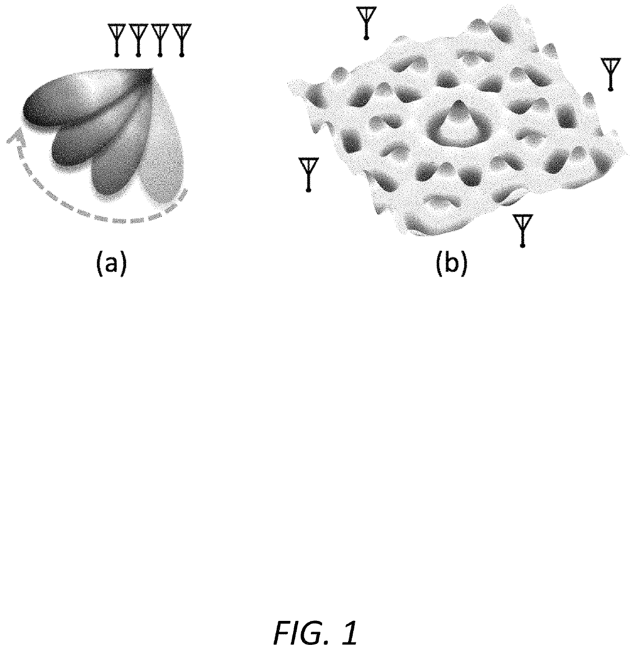
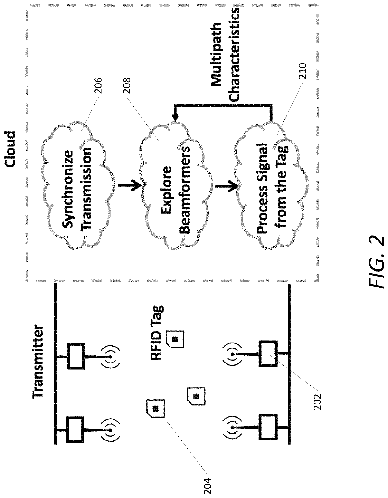
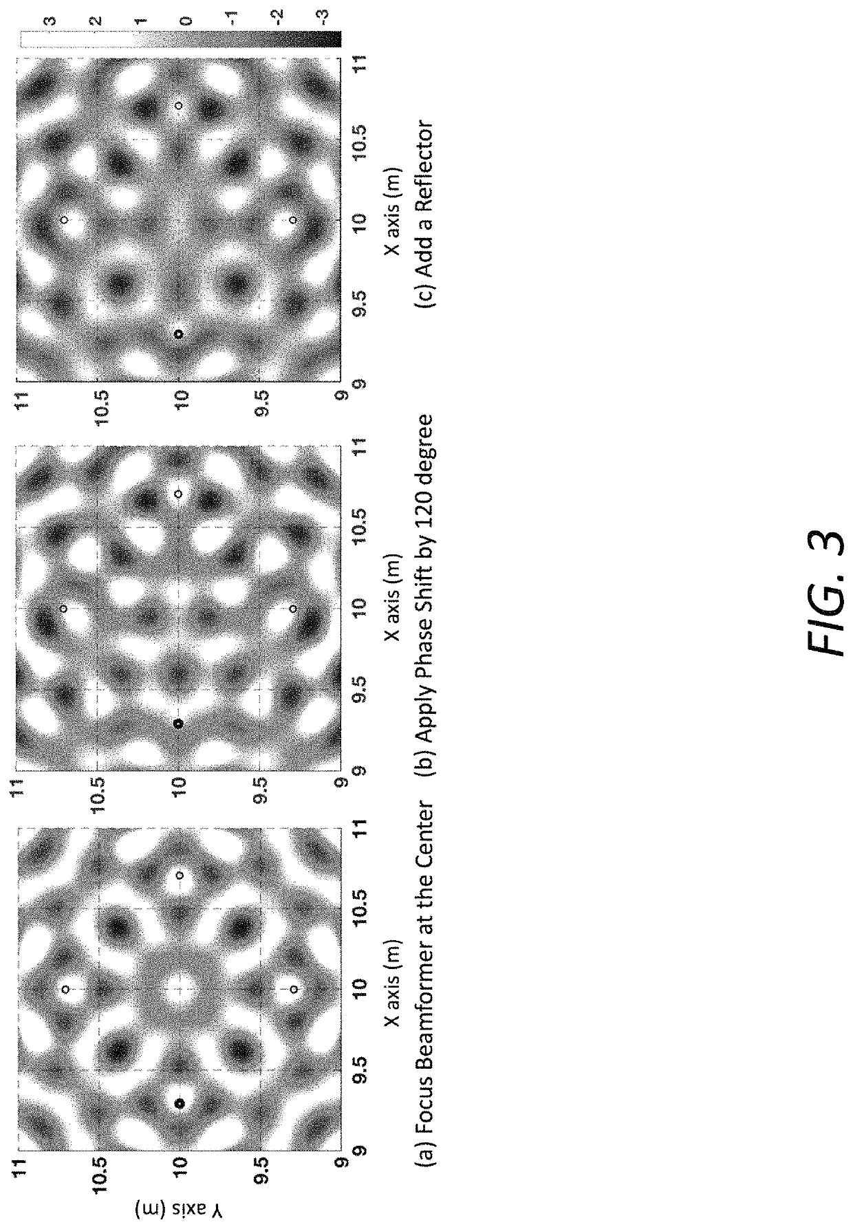
[0028]The novel systems and methods of the invention powers and communicates with commercial passive RFID tags via RF-backscatter from a plurality of distributed commercial RFID readers, where the tags may be beyond the communication range of any single reader. This is achieved by coherently combining signals across distributed RFID readers to maximize the received signal power at one or more RFID tags, whose location and orientation are initially unknown. Because RFID systems operate based on RF-backscatter, the method applies beamforming weights both on the transmitted and received signals to maximize energy both to and from the RFID tags. The RFID readers are connected to a wired backhaul, which allows them to coordinate transmissions and data that needs to be transmitted on the downlink. Additionally, while the locations of the RFID readers are known, th...


PUM


Abstract

A system that exploits collaboration between a plurality of spatially distributed RFID readers to enhance the range of commercial passive RFID tags, without alteration to the tags. The system uses distributed MIMO to coherently combine signals across geographically separated RFID readers. It is capable of inferring the optimal beamforming parameters to beam energy to a tag without any initial knowledge of the location or orientation of the tags.

Description

RELATED APPLICATIONS[0001]This application claims the benefit of U.S. Provisional Patent Application No. 62 / 931,880, filed Nov. 7, 2019, the contents of which are incorporated herein in their entirety.GOVERNMENT INTEREST[0002]This invention was made with U.S. government support under contract CNS 1718435, awarded by the National Science Foundation (NSF). The U.S. government has certain rights in the invention.BACKGROUND OF THE INVENTION[0003]Typical, prior art passive commercial RFID tags have a maximum range of about 5-15 meters. This limited range is due to several factors, including their limited cost, form-factor, and the FCC-mandated power limits of the RFID readers they harvest energy from. In many factories and warehouses, RFID-tagged products can only be detected around specific checkpoints in the vicinity of an RFID reader and are virtually undetectable at other points in between. Further, recent innovation on RFID-based localization and sensing remain constrained to a few ...

Claims


Application Information

Patent Timeline
Patent Type & Authority Patents(United States)
IPC IPC(8): G06K7/08G06K7/10G06K19/07H04L67/10
CPCG06K7/10475G06K19/0723H04L67/10G06K7/10089G06K7/10158G06K7/10178
Inventor KUMAR, SWARUNJIN, HAOJIANWANG, JINGXIANZHANG, JUNBOSAHA, RAJARSHI
Owner CARNEGIE MELLON UNIV
Why Eureka
Try Eureka