Cleanable volume displacement pipetter

a volume displacement, pipetter technology, applied in the field of scientific instruments, can solve the problems of affecting the performance of pipette, and affecting the quality of pipette,

Active Publication Date: 2005-10-27
VERTEX PHARMA INC
View PDF3 Cites 14 Cited by
  • Summary
  • Abstract
  • Description
  • Claims
  • Application Information

AI Technical Summary

Problems solved by technology

Yet it suffers from one major defect.
Despite all these measures, currently available cleaning methods are often not thorough enough and carry-over of reagents becomes a significant problem.
While this ...

Method used


Image

  • Cleanable volume displacement pipetter
  • Cleanable volume displacement pipetter
  • Cleanable volume displacement pipetter

Examples


Embodiment Construction

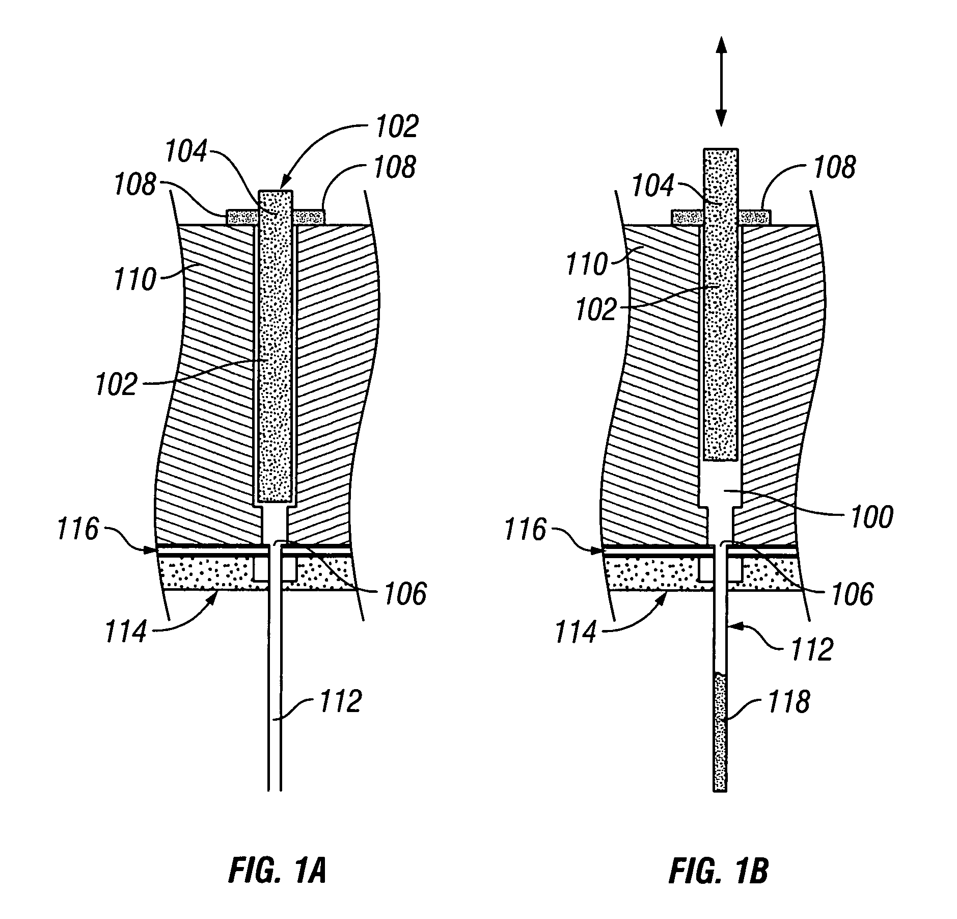
[0014] A typical pipette design used in array pipetters is depicted in FIG. 1. In this design, a piston barrel 100 is provided. A piston 102 is disposed within the piston barrel 100. The piston barrel 100 typically contains barrel openings 104 and 106 on the ends. The body of the piston 102 extends through opening 104. A seal 108 is provided at opening 104 to ensure that an airtight seal is formed between piston 104, seal 108, and pipette body 110. A cannula 112 is disposed at opening 106 to act as a fluid dispenser / aspirator. Optionally, the cannula 112 may be held in a tip carrier 114. A seal 116 may be used to provide an airtight seal between the seal 116, tip carrier 114, pipette body 110, and cannula 112. In operation, piston 102 can move up, as in position B in FIG. 1, to draw fluid 118 into cannula 112. Movement of the piston 102 down, as in position A in FIG. 1, will expel fluid 118 out of cannula 112.

[0015] The pipette design depicted in FIG. 1 may be used in a single stan...


PUM


Abstract

Disclosed herein is a volume displacement pipette that includes a channel within the piston. The channel allows for cleaning fluids to be continuously run through the pipette tip for cleaning the tip. One end of the channel may be closed during normal operation of the pipette. Multiple pipettes may be combined into an array pipetter.

Description

BACKGROUND OF THE INVENTION [0001] 1. Field of the Invention [0002] The present invention relates to the field of scientific instrumentation. More specifically, the present invention relates to pipettes and array pipetters. [0003] 2. Description of the Related Art [0004] The widespread adoption by the biotech, pharmaceutical, and life science industry of 96-well plates and its denser 384- and 1536-well descendants has stimulated the concomitant demand for pipetters that can take advantage of these formats. Indeed, there are a variety of fluid-handling devices on the market that are designed to pipette in and out of 96 or 384 wells simultaneously. These array pipetters have 96 or 384 tips arranged in rectangular arrays of 8×12 or 16×24, with 9-mm or 4.5-mm pitch, respectively. There are also devices that only address one column of the plate at a time; this allows for more flexibility at the cost of reduced throughput. [0005] Array pipetters typically are volume displacement devices d...

Claims


Application Information

Patent Timeline
IPC IPC(8): B01L3/02B01L99/00G01N35/10
CPCB01L3/0217B01L2400/0487B01L2400/0633B01L99/00G01N35/1074G01N2035/1006G01N35/1004B01L13/02
Inventor SINCLAIR, JAMES E.
Owner VERTEX PHARMA INC
Why Eureka
Try Eureka