Ratchet wrench operated conveniently

a ratchet wrench and convenient technology, applied in the field of ratchet wrenches, can solve the problems of uneven and convenient operation of the conventional ratchet wrench, and achieve the effect of reducing the disadvantage and/or obviating the disadvantag

Inactive Publication Date: 2005-10-27
STANLEY CHIRO INT
View PDF3 Cites 14 Cited by
  • Summary
  • Abstract
  • Description
  • Claims
  • Application Information

AI Technical Summary

Benefits of technology

[0006] The present invention is to mitigate and / or obviate the disadvantage of the conventional ratchet wrench.
[0007] The primary objective of the present invention is to provide a ratchet wrench having including a positioning plate to push the pawl member, thereby reducing the volume of the ratchet wrench efficiently.
[0008] Another objective of the present invention is to provide a ratchet wrench, wherein the urging spring is supported and guided by the guide shaft of the positioning plate, so that the positioning plate is not easily deformed, thereby facilitating movement of the urging spring in the positioning plate.
[0009] A further objective of the present invention is to provide a ratchet wrench that only needs to provide a limit spring to position the control knob rigidly and stably, so that the ratchet wrench has a simplified construction, thereby decreasing costs of fabrication.
[0011] A further objective of the present invention is to provide a ratchet wrench, wherein the control knob is rigidly and stably positioned in the receiving chamber of the drive head by the limit spring, thereby facilitating a user operating the control knob.

Problems solved by technology

In addition, the spring 28 is not supported by the control knob 26 efficiently, so that operation of the conventional ratchet wrench is not smooth and conveniently.

Method used


Image

  • Ratchet wrench operated conveniently
  • Ratchet wrench operated conveniently
  • Ratchet wrench operated conveniently

Examples


Embodiment Construction

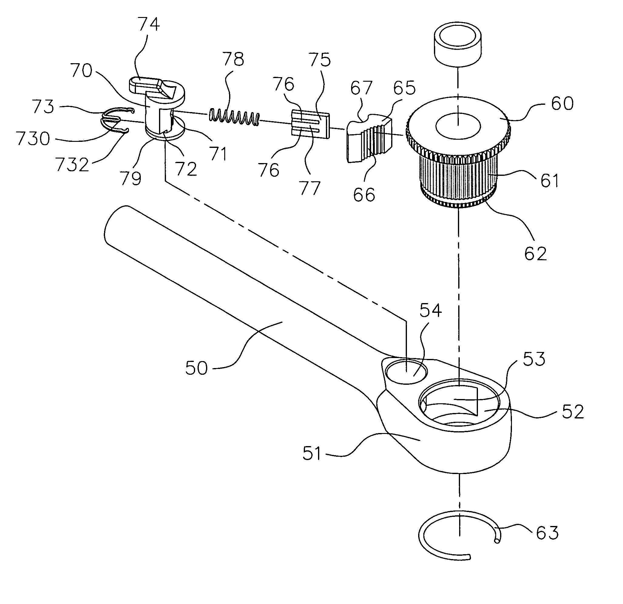
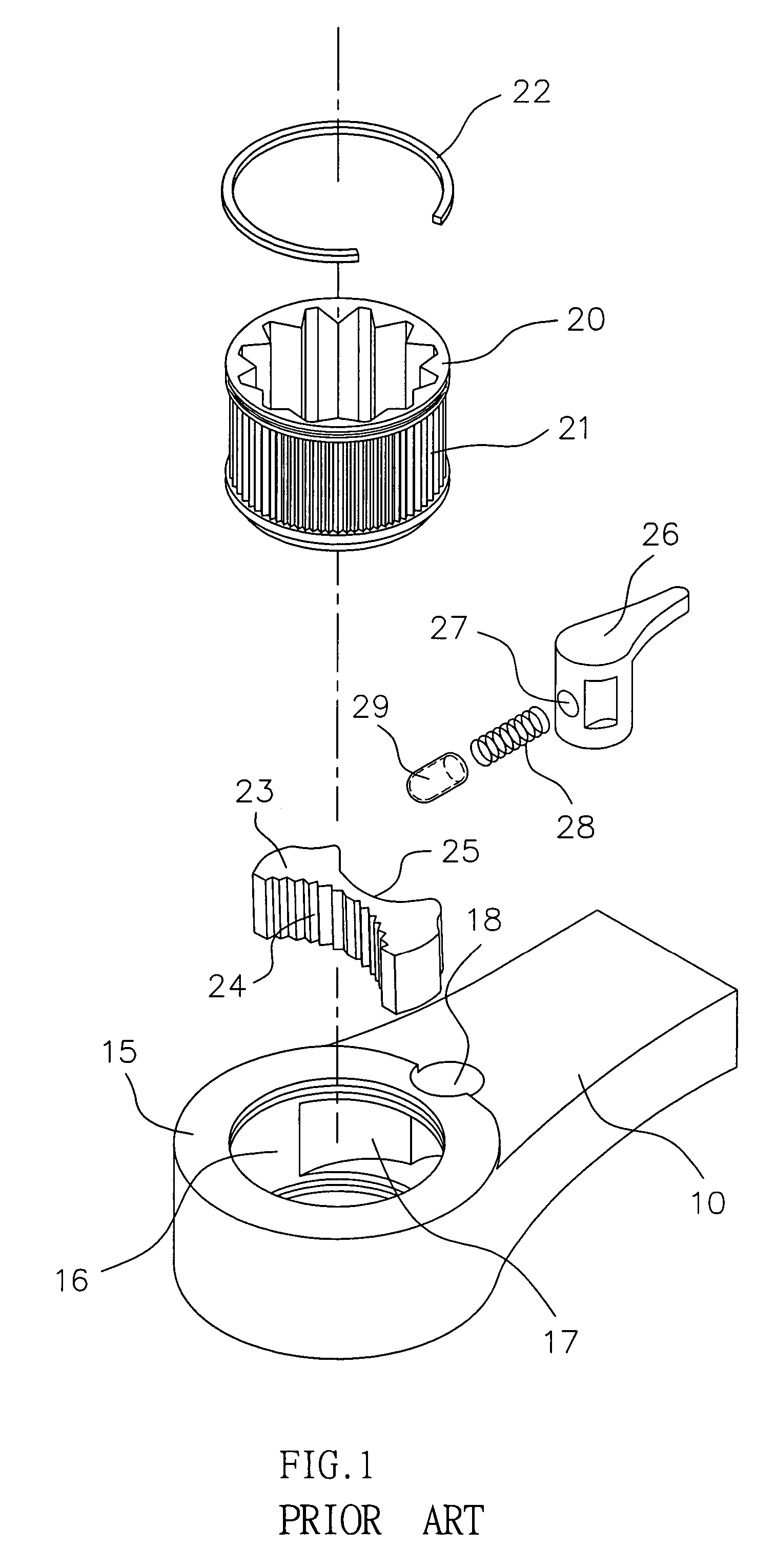
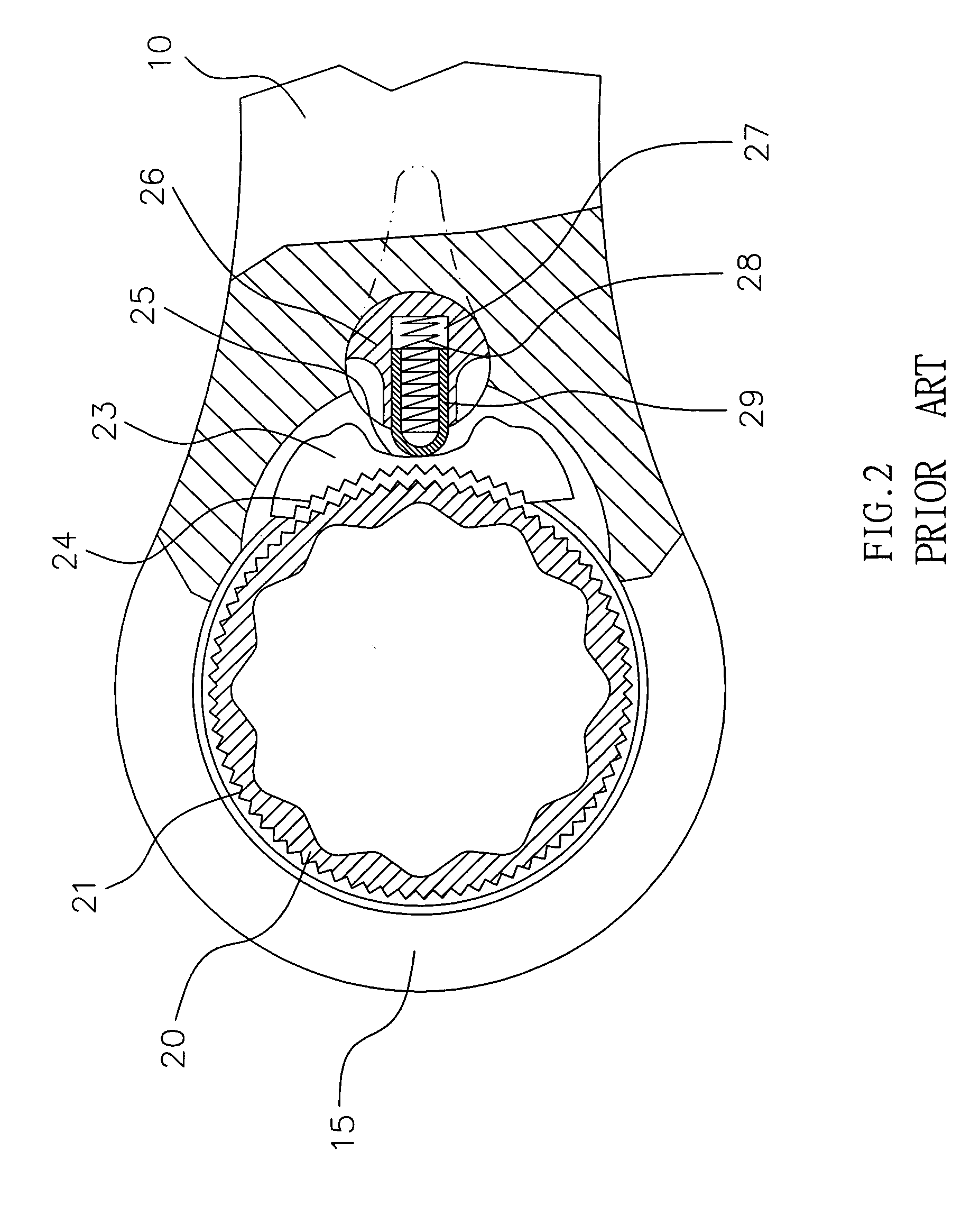
[0029] Referring to the drawings and initially to FIGS. 3-6, a ratchet wrench in accordance with the preferred embodiment of the present invention comprises a handle 50, a drive head 51 mounted on an end of the handle 50 and having a first end formed with a receiving hole 52, a mediate portion formed with a receiving recess 53 communicating with the receiving hole 52, and a second end formed with a receiving chamber 54 communicating with the receiving recess 53, a ratchet wheel 60 mounted in the receiving hole 52 of the drive head 51, a pawl member 65 pivotally mounted in the receiving recess 53 of the drive head 51 and engaged with the ratchet wheel 60, and a control knob 70 rotatably mounted in the receiving chamber 54 of the drive head 51 and rested on the pawl member 65 to push the pawl member 65 to press the ratchet wheel 60 to control the drive direction of the ratchet wheel 60. The above-mentioned structure and manner of operation are conventional and will not be further desc...


PUM


Abstract

A ratchet wrench includes a handle, a drive head, a ratchet wheel, a pawl member, a control knob, a positioning plate, and an urging spring. Thus, the ratchet wrench includes a positioning plate to push the pawl member, thereby reducing the volume of the ratchet wrench efficiently. In addition, the urging spring is supported and guided by the guide shaft of the positioning plate, so that the positioning plate is not easily deformed, thereby facilitating movement of the urging spring in the positioning plate.

Description

BACKGROUND OF THE INVENTION [0001] 1. Field of the Invention [0002] The present invention relates to a ratchet wrench, and more particularly to a ratchet wrench, wherein the urging spring is supported and guided by the guide shaft of the positioning plate, thereby facilitating operation of the ratchet wrench. [0003] 2. Description of the Related Art [0004] A conventional ratchet wrench in accordance with the prior art shown in FIGS. 1 and 2 comprises a handle 10, a drive head 15 mounted on a distal end of the handle 10 and having a first end formed with a receiving hole 16, a mediate portion formed with a receiving recess 17 communicating with the receiving hole 16, and a second end formed with a receiving chamber 18 communicating with the receiving recess 17, a ratchet wheel 20 mounted in the receiving hole 16 of the drive head 15 by a C-shaped snap 22 and having a periphery formed with a plurality of ratchet teeth 21, a pawl member 23 pivotally mounted in the receiving recess 17 o...

Claims


Application Information

Patent Timeline
Patent Type & Authority Applications(United States)
IPC IPC(8): B25B13/46
CPCB25B13/463
Inventor SHEN, RUI-CHI
Owner STANLEY CHIRO INT
Why Eureka
Try Eureka