Nasal ventilation interface and system

a ventilation interface and nasal tube technology, applied in the direction of breathing masks, inhalators, breathing protection, etc., can solve the problems of obstructive sleep apnea syndrome, affecting the sleep quality of patients, and affecting the quality of life of patients,

Inactive Publication Date: 2005-10-27
WOOD THOMAS J +1
View PDF88 Cites 89 Cited by
  • Summary
  • Abstract
  • Description
  • Claims
  • Application Information

AI Technical Summary

Problems solved by technology

However, in those individuals having a relatively smaller sized throat passage, the narrowed throat passage prohibits the adequate amount of oxygen from flowing into the lungs.
Additionally, a nasal obstruction, such as a relatively large tongue, and / or certain shapes of the palate and / or the jaw of the individual further prohibit the adequate amount of oxygen from flowing into the lungs.
As a result, the individual suffering from obstructive sleep apnea syndrome generally experiences fragmented sleep that is not restful.
The fragmented sleep results in one or more of excessive and / or inappropriate daytime drowsiness, headache, weight gain or loss, limited attention span, memory loss, poor judgment, personality changes, lethargy, inability to maintain concentration, and / or depression.
Further, prior to, during, and / or subsequent to certain medical procedures and / or medical treatments, an individual can be unable to receive the adequate amount of oxygen.
As a result, the harness is generally uncomfortable to wear, particularly when sleeping.
The applied pressure often results in undesirable irritation and sores caused by movement of the mask and harness during periods of both wakefulness and sleep.
Further, the required seal is generally difficult to maintain when the mask and harness is moved.
The mask also generally applies an undesirable pressure to the sinus area that is adjacent to the nose, causing the nasal sinus airways to narrow.
Additionally, the tubing may fold undesirably exacerbating the above problem.
The above-discussed combination of increased flow velocity and decreased pressure results in the removal of moisture from the mucosal walls during inspiration and may cause an undesirable drying and a burning sensation within the nares.
As a result, the individual may remove the mask to alleviate these discomforts, consequently discontinuing the beneficial application of the positive pressure.
Additionally the decreased pressure and increased air flow velocity deteriorate the laminar flow between the air input and output portions of the conventional mask.

Method used


Image

  • Nasal ventilation interface and system
  • Nasal ventilation interface and system
  • Nasal ventilation interface and system

Examples


Embodiment Construction

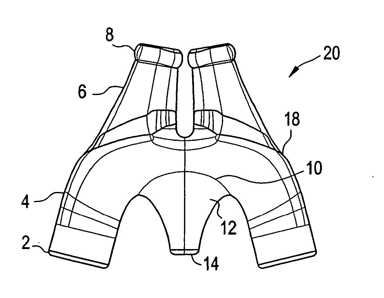
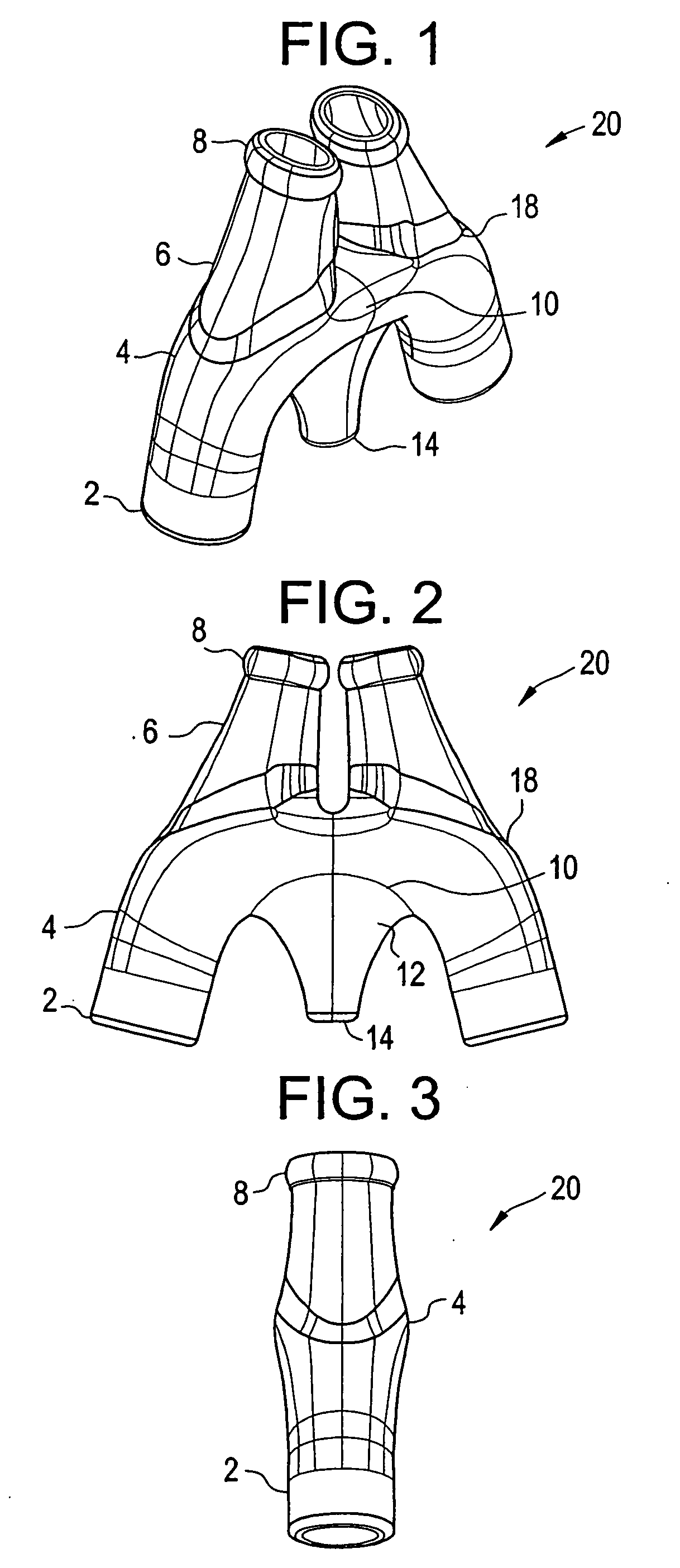
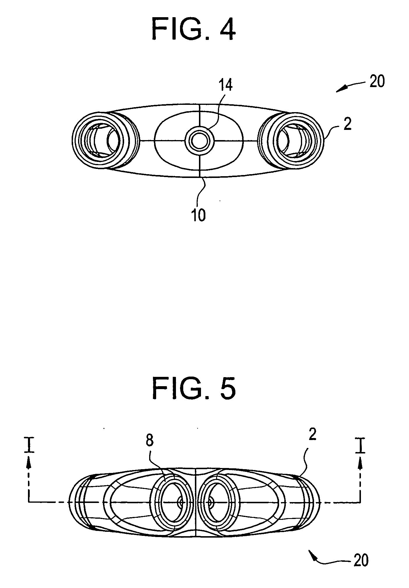
[0012] A first exemplary embodiment of the present invention provides a nasal ventilation interface including a cannula connectable to a source of ventilation gas via at least two ventilation connectors including at least one reservoir flange in close proximity with at least one nasal insert. The nasal ventilation interface further includes a seal portion positioned on a distal end of the at least one nasal insert and a central reservoir with at least one exhaust flange and an exhaust port positioned at a midpoint between the at least two ventilation connectors.

[0013] In a second exemplary embodiment, a nasal ventilation interface includes a cannula connectable to a source of ventilation gas via at least two ventilation connectors forming a first inflow portion. A reservoir flange forms a second inflow portion with at least one nasal insert. The nasal insert forms a third inflow portion and a first outflow portion. A seal portion with a substantially oval cross section is positione...


PUM


Abstract

A ventilation interface and system is described which can be adapted to be connected to a source of ventilation. The ventilation interface and system may include variable exhaust ports. The ventilation interface system may optionally include feed tubes, y-connector, tube holder, and headgear.

Description

CROSS-REFERENCE TO RELATED APPLICATION [0001] This application is a continuation in part of application Ser. No. 10 / 830,034 filed Apr. 23, 2004 and claims benefit under 35 U.S.C. 120. Additionally, this application claims the benefit to U.S. Provisional Patent Application No. 60 / 501,028, entitled “Ultimate Performance Cannula,” filed Sep. 9, 2003, and U.S. Provisional Patent Application No. 60 / 492,282, entitled “Variable Exhaust Ports,” filed Aug. 5, 2003, the disclosures of which are expressly incorporated by reference herein in their entirety.BACKGROUND OF THE INVENTION [0002] 1. Field of the Invention [0003] Exemplary embodiments of the invention are directed to a nasal ventilation interface adaptable to be connected to a source of ventilation. [0004] 2. Discussion of Related Art [0005] Obstructive sleep apnea syndrome (commonly referred to as obstructive sleep apnea, sleep apnea syndrome, and / or sleep apnea) is a medical condition which includes repeated, prolonged episodes of c...

Claims


Application Information

Patent Timeline
Patent Type & Authority Applications(United States)
IPC IPC(8): A61M16/06A61M16/08A61M16/20A62B7/00A62B18/02
CPCA61M16/0666A61M16/0833A61M16/20A61M16/08
Inventor WOOD, THOMAS J.HERNANDEZ, SHARA
Owner WOOD THOMAS J
Why Eureka
Try Eureka