Filter assembly for a liquid dispensing apparatus

a liquid dispensing apparatus and filter assembly technology, applied in the direction of filtration separation, separation processes, coatings, etc., can solve the problems of periodic clogging or failure of the liquid dispenser, affecting and affecting the efficiency so as to minimize the downtime and cost, quick and convenient removal, the effect of optimizing the productivity of the liquid dispensing system

Inactive Publication Date: 2005-10-27
NORDSON CORP
View PDF7 Cites 28 Cited by
  • Summary
  • Abstract
  • Description
  • Claims
  • Application Information

AI Technical Summary

Benefits of technology

[0010] In an exemplary embodiment of the invention, the first connecting member comprises a retaining slot and the second connecting member comprises a tab. The tab engages the retaining slot to movably couple the closure element to the filter element. The first and second connecting members may advantageously be configured to releasably couple the closure element and the filter element. In this way, the filter element may be quickly and conveniently uncoupled from the closure element and replaced with a new or rebuilt filter element. To this end, the retaining slot has a U-shaped configuration with an open end for receiving the tab. In the exemplary embodiment of the invention, the closure element, filter element and biasing member are axially aligned along a generally longitudinal axis. The U-shaped slots have first and second axial legs connected by a third transverse leg. The closure element is moveable in the axial direction when the tab engages the first and second legs and moveable in the transverse direction when the tab engages the third leg.
[0013] To limit the movement of the closure element while in the connected position, the shoulder may further include a locking pin extending from the second edge portion. The lip of the filter housing may also include a pin recess. When in the connected position, the locking pin engages the pin recess thereby limiting the movement of the closure element relative to the filter housing. Moreover, to move between the connected and disconnected positions, the closure element is first moved axially along the longitudinal axis toward the filter housing so as to position the locking pin below the lip of the filter housing, and is then rotated relative to the filter housing. In this way, the filter assembly of the invention may be quickly and conveniently removed from the filter housing. The filter assembly of the present invention minimizes the downtime and costs associated with the removal, replacement, repair and / or cleaning of the filter element for optimizing the productivity of the liquid dispensing system.

Problems solved by technology

Under certain operating conditions, particles can accumulate in the viscous liquid and cause the liquid dispenser to periodically become clogged or fail.
This prolonged exposure to heat in an oxygen-containing environment may cause at least a portion of the viscous liquid to char, oxidize, or otherwise degrade.
The viscous liquid may also be contaminated by particles generated by the manufacturing operations associated with the liquid dispensing operation.
Particulate contamination in the supply of viscous liquid can disrupt the operation of the liquid dispenser.
Particles may also become trapped between the valve and valve seat of the valve assembly and disrupt the metering of precise amounts of viscous liquid.
The downtime of the adhesive dispensing operation associated with the removal, replacement, repair, cleaning, and reinstallation of the filter element results in lost productivity.
If the filter element is difficult to remove or reinstall, the servicing downtime further reduces productivity.
Both result in additional downtime and lost productivity.
Perhaps the most significant impact of a time delay in servicing the filter element is that the viscous liquid in the holding tank remains static and exposed to an oxidizing atmosphere.
This further increases particulate contaminants generated by the degrading liquid.
If a filter element is difficult to remove from the manifold block, maintenance personnel may be reluctant to replace or clean the filter element.
Eventually, the increase in operating pressure may damage either the liquid dispenser or other sensitive components of the dispensing system.

Method used


Image

  • Filter assembly for a liquid dispensing apparatus
  • Filter assembly for a liquid dispensing apparatus
  • Filter assembly for a liquid dispensing apparatus

Examples


Embodiment Construction

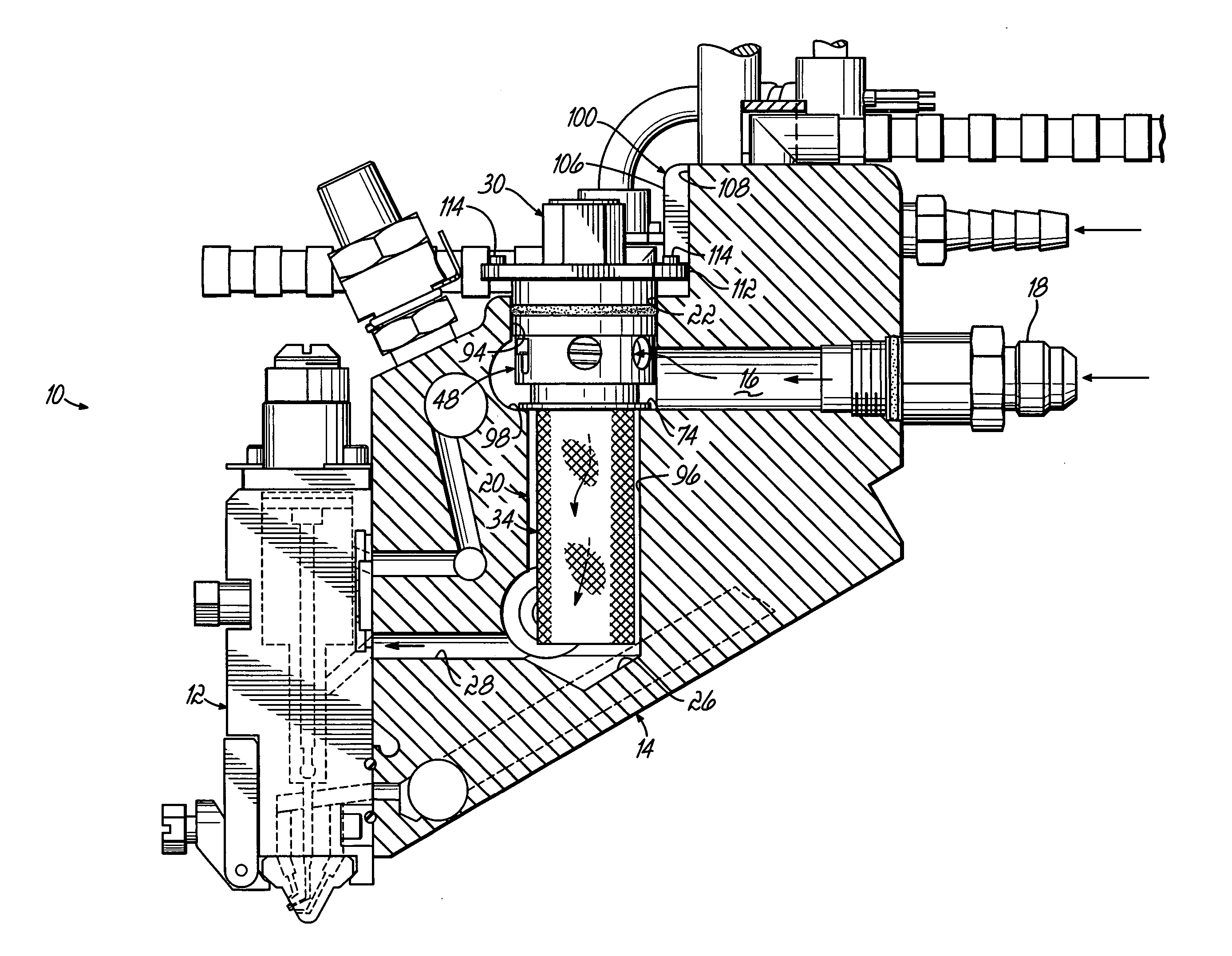
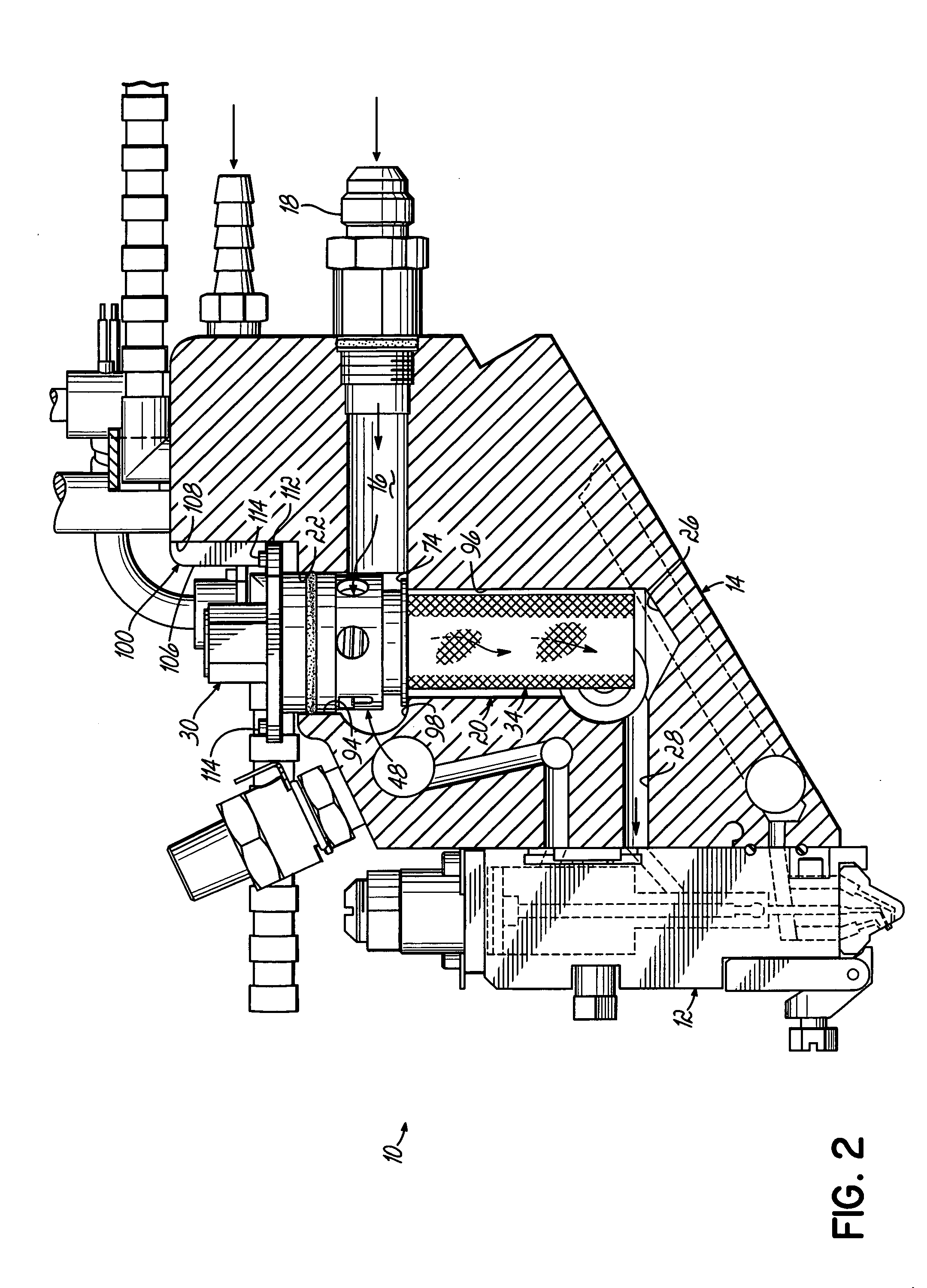
[0022] According to the invention, a filter assembly for use with a liquid dispensing apparatus permits simplified and convenient insertion and removal from the liquid dispensing apparatus. The spring biasing incorporated into the filter assembly minimizes the downtime associated with the removal, replacement, repair and / or cleaning of the filter assembly and thereby optimizes the productivity of the liquid dispensing operation. It will be appreciated that the present invention may be applied to various apparatus operable for dispensing liquids.

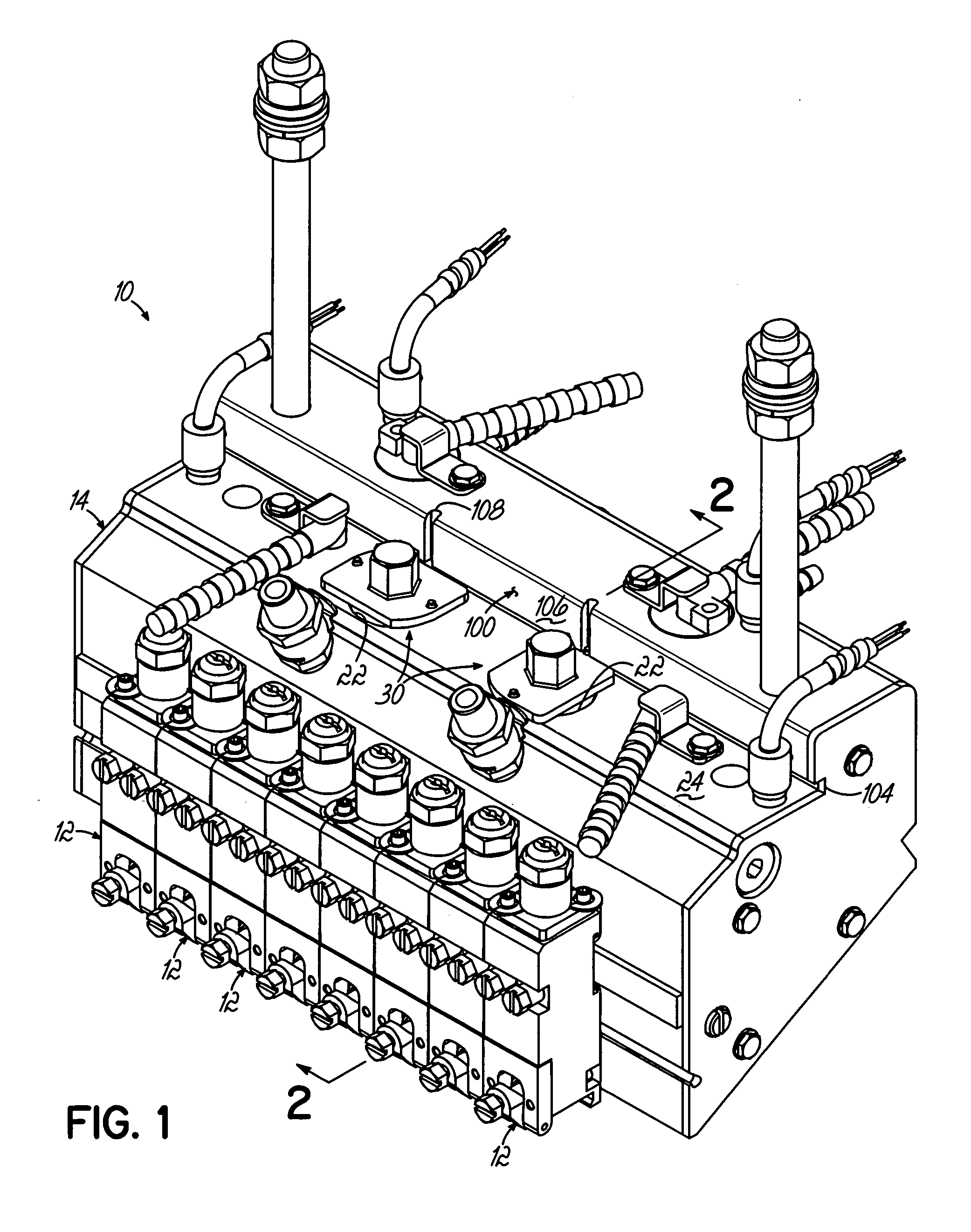
[0023] Referring to FIG. 1, a liquid dispensing apparatus is indicated generally by reference numeral 10. Typically, the liquid dispensing apparatus 10 comprises a plurality of dispensing modules 12 removably attached to a filter housing 14. The dispensing modules 12 receive filtered liquid from the filter housing and in turn dispense or apply the filtered liquid onto a substrate. The dispensing module 12 includes an internal valve assembly ...


PUM

PropertyMeasurementUnit
angleaaaaaaaaaa
distanceaaaaaaaaaa
movementaaaaaaaaaa

Abstract

A spring-biased filter assembly for a liquid dispenser is disclosed that permits ready removal of a filter assembly from a filter housing. The filter housing includes a liquid inlet, a liquid outlet, and a liquid passageway therebetween. The filter housing also has an opening in communication with the liquid passageway. The filter assembly comprises a closure element positioned in the opening and releasably coupled to the filter housing through movement between connected and disconnected positions with respect to the filter housing. A filter element is positioned in the liquid passageway and coupled to the closure element. A biasing member is coupled to the closure element and the filter element and biases the closure element into the connected position.

Description

FIELD OF THE INVENTION [0001] The present invention generally relates to filter assemblies and, more specifically, to filter assemblies used in viscous liquid dispensing systems. BACKGROUND OF THE INVENTION [0002] Viscous liquids are applied by dispensers onto a surface of a substrate in a variety of dispensing applications employed in the manufacture of products and product packaging. These viscous liquids include thermoplastic materials such as hot melt adhesives. Liquid dispensers utilize pneumatically or electrically actuated valve assemblies for metering a precise quantity of the viscous liquid and discharging the metered amount through a small-diameter dispensing orifice. Many thermoplastic materials exist in a solid form at room or ambient temperature and must be heated to create a flowable viscous liquid. Typically, the solid form of material is placed in a holding tank having heated walls and is melted by heating the solid material above its melting point. The viscous liqui...

Claims


Application Information

Patent Timeline
Patent Type & Authority Applications(United States)
IPC IPC(8): B01D29/23B01D35/30B29C48/03B29C48/694
CPCB01D29/23B29C47/687B29C47/0009B01D2201/4015B05C5/0279B29C48/03B29C48/694
Inventor GOULD, MARK A.JONES, KENNETH
Owner NORDSON CORP
Why Eureka
Try Eureka