Disposable test tube rack

a test tube rack and disposable technology, applied in the field of inexpensive disposable test tube racks, can solve the problems of more expensive, and achieve the effects of compact and convenient storage, convenient inspection and observation of the contents of containers, and preventing tipping and spilling

Inactive Publication Date: 2005-10-27
WHITNEY PROD
View PDF18 Cites 93 Cited by
  • Summary
  • Abstract
  • Description
  • Claims
  • Application Information

AI Technical Summary

Benefits of technology

[0008] It is therefore a principal object of the invention to provide an improved test tube rack and covered container, made of inexpensive injection-molded or thermoformed plastic, such as PVC (polyvinyl chloride) (utility and virgin), rPVC (recycled polyvinyl choride), and rPET (recycled polyethylene terapthalate), or other materials, for instance polystyrene (PS) or polycarbonate (PC). The ideal material of these is rPVC, although it is more expensive. These plastics can be made in transparent form to readily allow inspection and observation of the container's contents.
[0009] Another object of the invention is to provide such a container comprising only three or four parts, comprising a tray, a cover, a central support panel and / or a lower support panel, of which two (the tray and cover) are identical shells. The assembled test tube rack has sufficient depth to accommodate test tubes, or other axially elongated articles, of varying height, while the central support panel and the lower support panel provide positive positioning and support to each test tube or article, to prevent tipping and spilling during shipping and handling. A related object is to provide such a container in which the identical shells (the tray and the cover) are nestable, for compact and convenient storage, and to reduce the total number of different components which a laboratory must keep on hand. Alternatively, a tray may be utilized without a cover, in applications where the cover is not needed.
[0010] As a further object of the invention, the identical tray and cover shells are provided at their adjoining flanges with cooperating tabs and depressions which allow the trays and covers to be snapped together (either with or without the central support panel sandwiched between them) to positively hold the test tube rack together, thereby preventing inadvertent tipping and sliding of its contents.
[0011] Another desirable feature of the invention is that when a technician is finished with a batch of test tubes in a certain tray, the batch of test tubes may be disposed of as a unit merely by snapping a cover over them to prevent tipping and spilling as they are taken to a disposal point such as a biohazard trash can or sharps container.

Problems solved by technology

The ideal material of these is rPVC, although it is more expensive.

Method used


Image

  • Disposable test tube rack
  • Disposable test tube rack
  • Disposable test tube rack

Examples


second embodiment

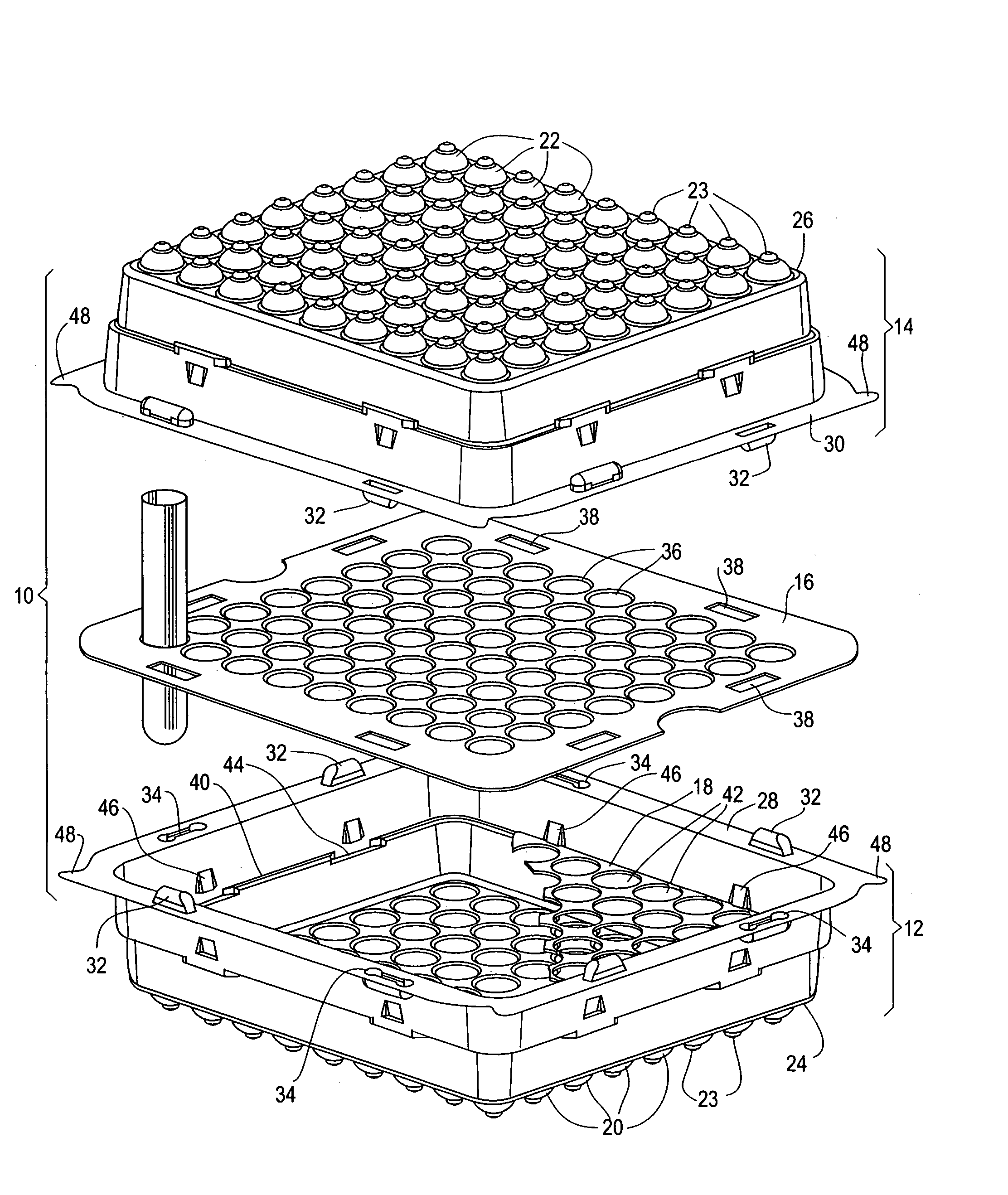
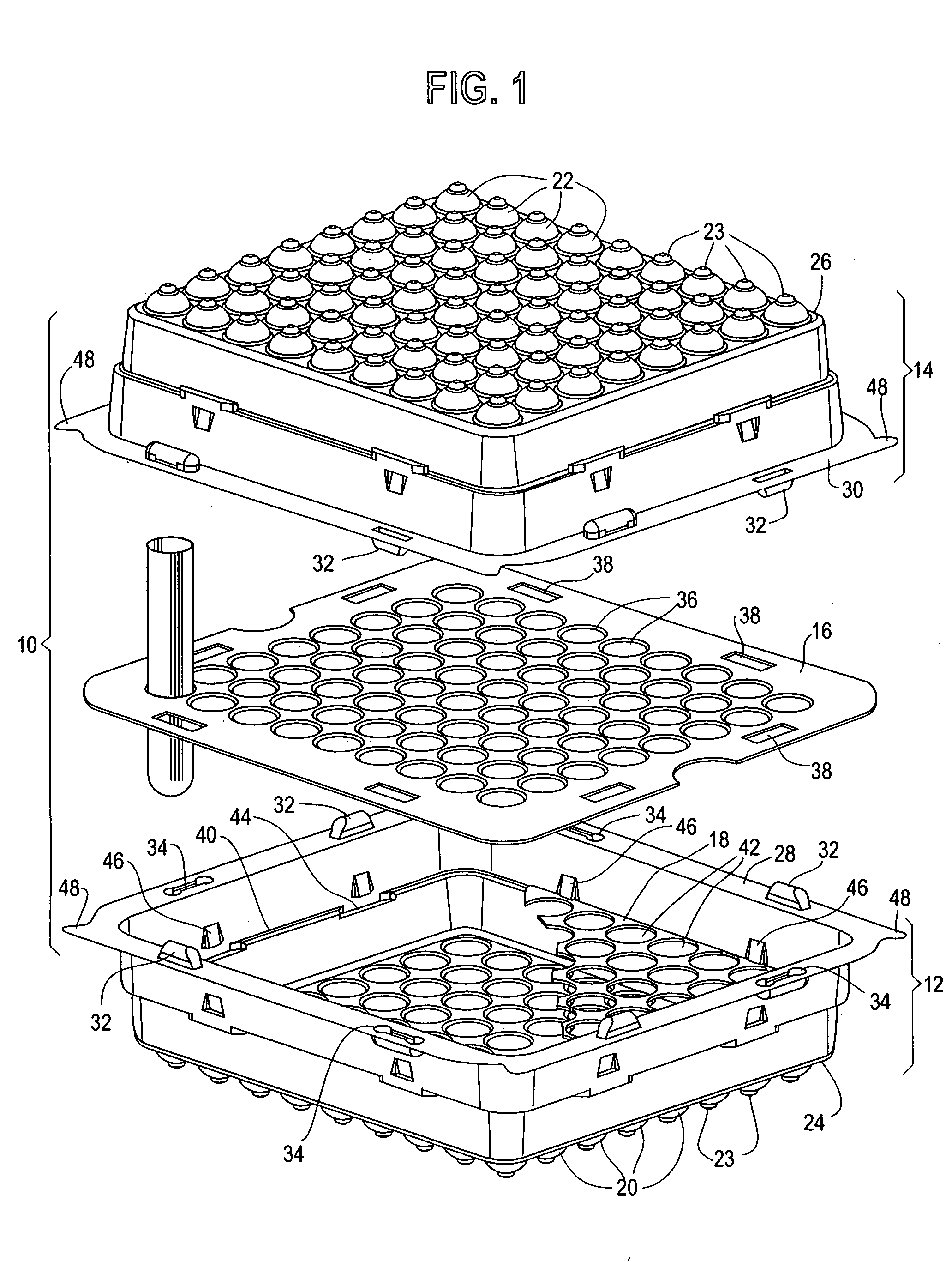
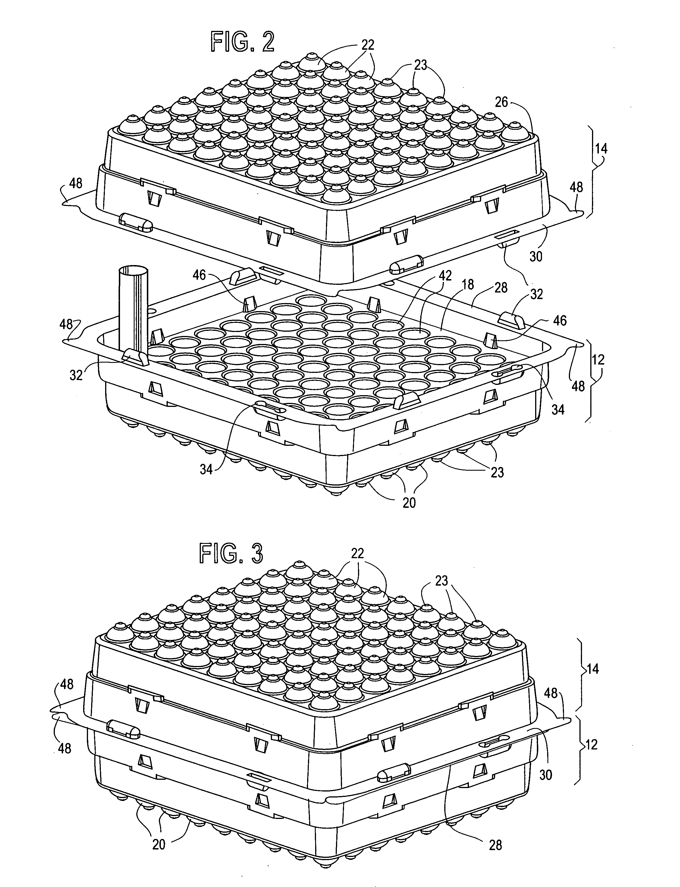
[0032]FIGS. 6-8 show a second preferred embodiment of the improved test tube rack. FIG. 6 shows an exploded view of the three components of the this second embodiment of the improved test tube rack 100 comprising a first shell serving as a tray 112, a second shell serving as a cover 114, and the central support panel 116.

[0033] The first and second shells are identical pieces and form the tray 112 and the cover 114. The tray 112 and the cover 114 each have an array of hemispherical protrusions corresponding to the positions of the test tubes to be contained within. As a tray 112, the protrusions become wells 120 to cradle and position the test tubes. As a cover 114, the protrusions become domes 122, which fit over, and thereby position, a test tube long enough to touch at both the top of the cover 114 and the bottom of the tray 112. The wells 120 and domes 122 also have an additional protrusion forming a pocket 123 which, when the shell is a tray 112, serves to catch spilled materia...

first embodiment

[0037] An additional feature applicable to the invention is shown in FIG. 9, which illustrates a dual-purpose support panel 216 having perforated edge strips 247 which can be easily separated by hand and removed. As supplied with the tray assembly, the support panel 216 serves the purpose of the central support panel 16 of FIG. 1, and has openings 238 adapted to engage the tabs 32 of the tray 12. By simply separating the edge strips at their perforations, the external dimensions of the separator 14 are reduced sufficiently to fit into the lower shell 12 and whereby it can rest on the ledge 40 (FIGS. 4) and serve as the lower support panel 18.

[0038] In practice, the test tube rack of the first preferred embodiment is supplied with two dual-purpose support panels 216, which at the option of the user can employed in several ways. For example, if only one support panel is required, the other can be discarded. If extra support is needed, the two support panels 216 can be superimposed and...


PUM


Abstract

A test tube rack for supporting, storing and carrying a plurality of test tubes in a laboratory environment comprising a tray, a central support panel and/or lower support panel and a cover. The tray and cover are identical and interchangeable, and tapered for storage in nested stacks. Wells in the tray bottom are in alignment with corresponding openings in the central support panel and corresponding holes in the lower support panel and with domes in the cover, and serve to locate and retain test tubes within the test tube rack. The cover snap-attaches to the tray by means of at least one molded-in tab on the tray or cover which is received and frictionally retained by a corresponding well on the opposite element, thereby locating and securing the cover to the tray, and also locating and securing the central support panel between the tray and the cover. A dual-purpose support panel has manually removable perforated edges allowing it to serve either as a central support panel or, with the perforated edges removed, as a lower support panel. The test tube rack is preferably made of transparent injection-molded or thermoformed plastic.

Description

FIELD OF THE INVENTION [0001] This invention relates to improvements in an inexpensive disposable test tube rack suitable for safely storing and carrying a plurality of test tubes, or other axially elongated articles, in supported, separated, upstanding relationship to each other. BACKGROUND OF THE INVENTION [0002] In a laboratory environment, particularly in laboratories working with biologically active materials, it is important to have a secure means of supporting an array of test tubes, often in a predetermined order, and of transporting and storing them between uses. Among the desirable features in such a product are: transparency, so that the test tubes and their contents are readily visible; nestability, so that the parts of the test tube rack may be compactly nested when not in use; stackability, so that assembled test tube racks may be stacked one on top of the other for storage; and disposability, so that a rack containing a group of used test tubes may be disposed of as a...

Claims


Application Information

Patent Timeline
Patent Type & Authority Applications(United States)
IPC IPC(8): A47B73/00B01L9/06
CPCB01L9/06B01L2300/041B01L2200/18
Inventor WHITNEY, STEVEN G.
Owner WHITNEY PROD
Why Eureka
Try Eureka