Apparatus

a technology of polar modulation and transmission apparatus, applied in the field of polar modulation transmission apparatus, can solve the problems of reducing the frequency response time of the pll, affecting the quality of the signal, and the risk of deteriorating the noise characteristics of the pll, so as to suppress the interference of other wireless equipment, high accuracy, and high quality transmission signals

Active Publication Date: 2005-10-27
PANASONIC CORP
View PDF22 Cites 9 Cited by
  • Summary
  • Abstract
  • Description
  • Claims
  • Application Information

AI Technical Summary

Benefits of technology

[0018] Furthermore, to achieve the above-stated object of the present invention, there are provided a wireless transmission apparatus and a wireless communication apparatus comprising the frequency modulation apparatus of the above configuration. By this means, the wireless transmission app

Problems solved by technology

However, widening the PLL bandwidth has the risk of deteriorating noise characteristics.
On the other hand, although widening the bandwidth too much makes it possible to avoid adversely affecting the modulation signal, this in turn makes it difficult to suppress n

Method used


Image

  • Apparatus
  • Apparatus
  • Apparatus

Examples


embodiment 1

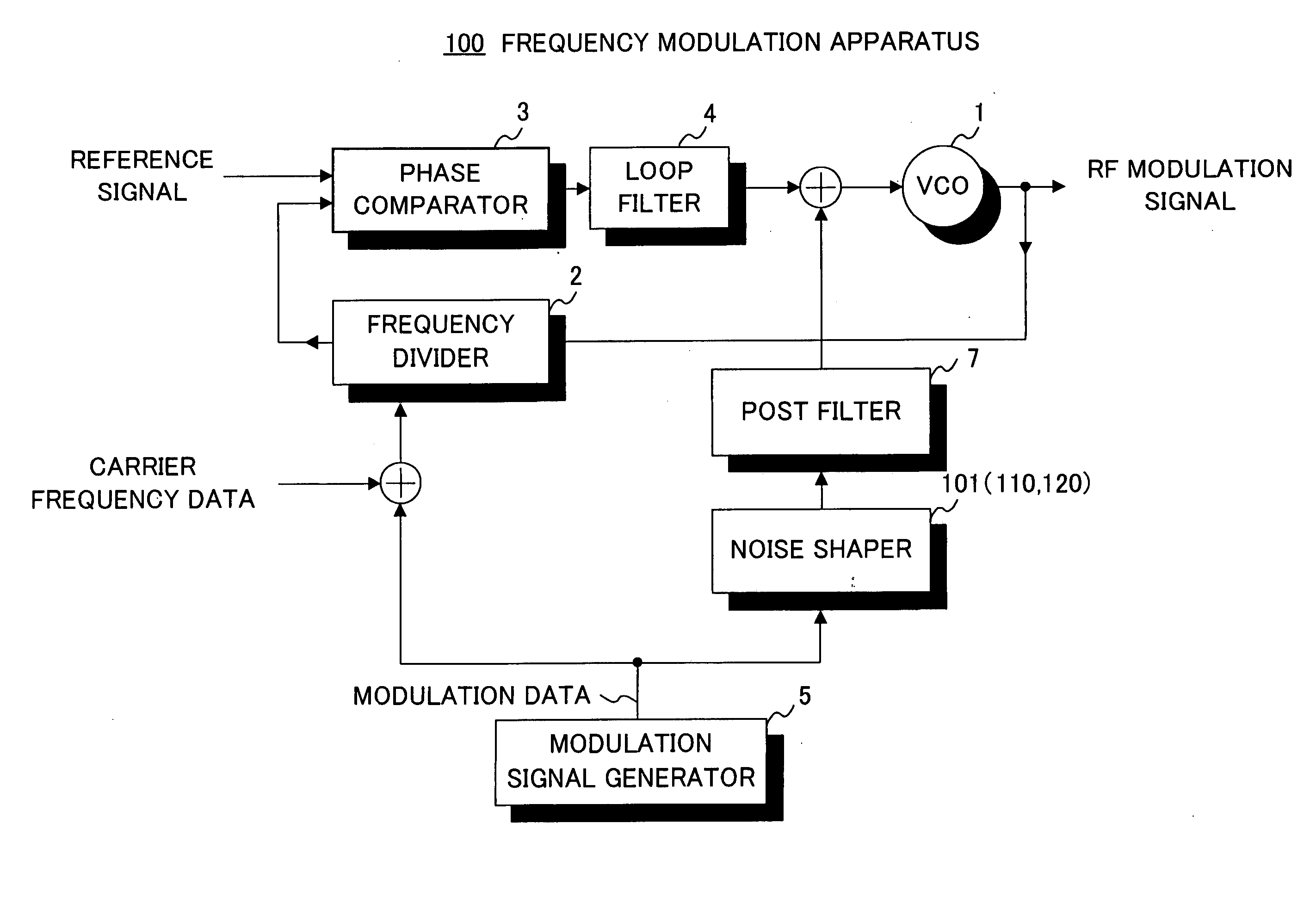
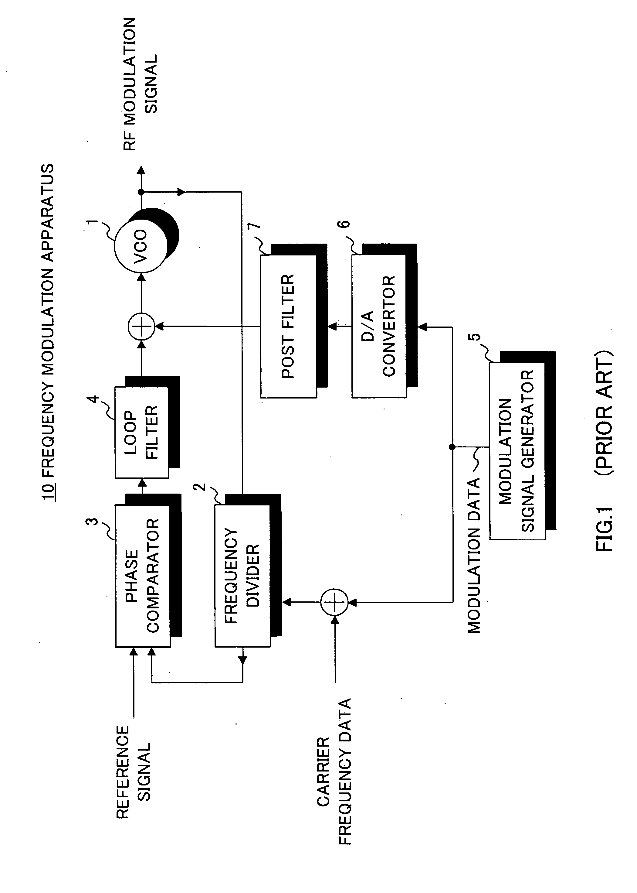
[0038]FIG. 4 shows the configuration of the two-point frequency modulation apparatus according to Embodiment 1 of the present invention, wherein parts that are identical to those in FIG. 1 are assigned the same reference numerals as in FIG. 1. In comparison to frequency modulation apparatus 10 of FIG. 1, frequency modulation apparatus 100 of FIG. 4 has noise shaper 101 instead of D / A convertor 6.

[0039] Noise shaper 101 has the function of shaping analogue voltage values in accordance with modulation data (i.e. digital baseband modulation signals) and the function of changing the frequency characteristics of the quantization noise that appears then.

[0040] Noise shaper 101 of this embodiment is configured as shown in FIG. 5. In this FIG. 5, X represents modulation data and Y represents analogue output voltage. Noise shaper 101 has, roughly, differentiator 102 that differentiates modulation data; quantizer 103; and feedback circuit 104 that synchronizes the timing of the output signa...

embodiment 2

[0049] The present embodiment proposes the use of a bandpass delta sigma modulator having the configuration shown in FIG. 8 as a noise shaper. Noise shaper 110 is used in frequency modulation apparatus 100 in place of noise shaper 101 of FIG. 1.

[0050] Similar to noise shaper 101 of Embodiment 1, noise shaper 110 has the function of shaping analogue voltage values in accordance with modulation data and the function of changing the frequency characteristics of the quantization noise that appears then. However, the method of changing the frequency characteristics of quantization noise is different from that of Embodiment 1.

[0051] Noise shaper 110 inputs modulation data in subtractor 111 and inputs the subtraction result in filter (F(z)) 112 having oscillation characteristics such as shown in FIG. 9. The filter output is quantized in quantizer 113 and thereby becomes analogue output voltage Y. Furthermore, analogue output voltage Y is delayed in delay element 114 by z−1 and thereafter...

embodiment 3

[0058] The present embodiment proposes the use of a delta modulator having the configuration shown in FIG. 12 as a noise shaper. Noise shaper 120 is used in frequency modulation apparatus 100 in place of noise shaper 101 of FIG. 4.

[0059] Similar to noise shaper 101 and noise shaper 110 of Embodiment 1 and Embodiment 2, respectively, noise shaper 120 has the function of shaping analogue voltage values in accordance with modulation data and the function of changing the frequency characteristics of the quantization noise that appears then. However, the method of changing the frequency characteristics of quantization noise is different from those of Embodiment 1 and Embodiment 2.

[0060] Noise shaper 120 inputs modulation data in quantizer 122 via subtractor 121. Quantizer 122 quantizes the input signal at a sampling frequency at least double the sampling frequency of the modulation data and obtains an analogue voltage. In fact, quantizer 122 is designed to perform quantization at a sam...


PUM


Abstract

A two-point frequency modulation apparatus is proposed whereby the spectrum of transmission waves is kept within the spectrum mask. Voltage is supplied to the control voltage terminal of VCO 1 in accordance with modulation data via noise shaper 101 that has operating characteristics of attenuating more noise at higher frequencies. As a result, by virtue of the working of noise shaper 101, the signal level outputted from the PLL circuit combining the modulation signal and the quantization noise decreases in proportion to the distance form the central frequency, so that two-point frequency modulation apparatus 100 is made possible whereby the spectrum of an RF modulation signal is kept within the spectrum mask.

Description

BACKGROUND OF THE INVENTION [0001] 1. Field of the Invention [0002] The present invention relates specifically to a frequency modulation apparatus, polar modulation transmission apparatus, wireless transmission apparatus, and wireless communication apparatus that perform frequency modulation by utilizing the PLL (Phase Locked Loop). [0003] 2. Description of the Related Art [0004] Heretofore, frequency modulation apparatuses utilizing the PLL have been widely used to modulate carrier signals with baseband modulation signals and form transmission signals (that is, to up-convert baseband modulation signals to radio frequency). Generally, frequency modulation apparatuses of this type are expected to realize low costs, low power consumption, excellent noise characteristics, and high modulation accuracy. To modulate signals using the PLL, and, in particular, to improve modulation accuracy using the PLL, the PLL frequency bandwidth (i.e. PLL bandwidth) is preferably wider than the frequenc...

Claims


Application Information

Patent Timeline
IPC IPC(8): H03C3/09H03L7/00
CPCH03C3/0925H03C3/095H03C3/0941H03C3/0933
Inventor HIRANO, SHUNSUKEARAYASHIKI, MAMORU
Owner PANASONIC CORP
Why Eureka
Try Eureka