Inkjet recording apparatus
- Summary
- Abstract
- Description
- Claims
- Application Information
AI Technical Summary
Benefits of technology
Problems solved by technology
Method used
Image

Examples
Embodiment Construction
[0022] A first preferred embodiment in accordance with the invention will now be described, referring to FIGS. 1 to 3.
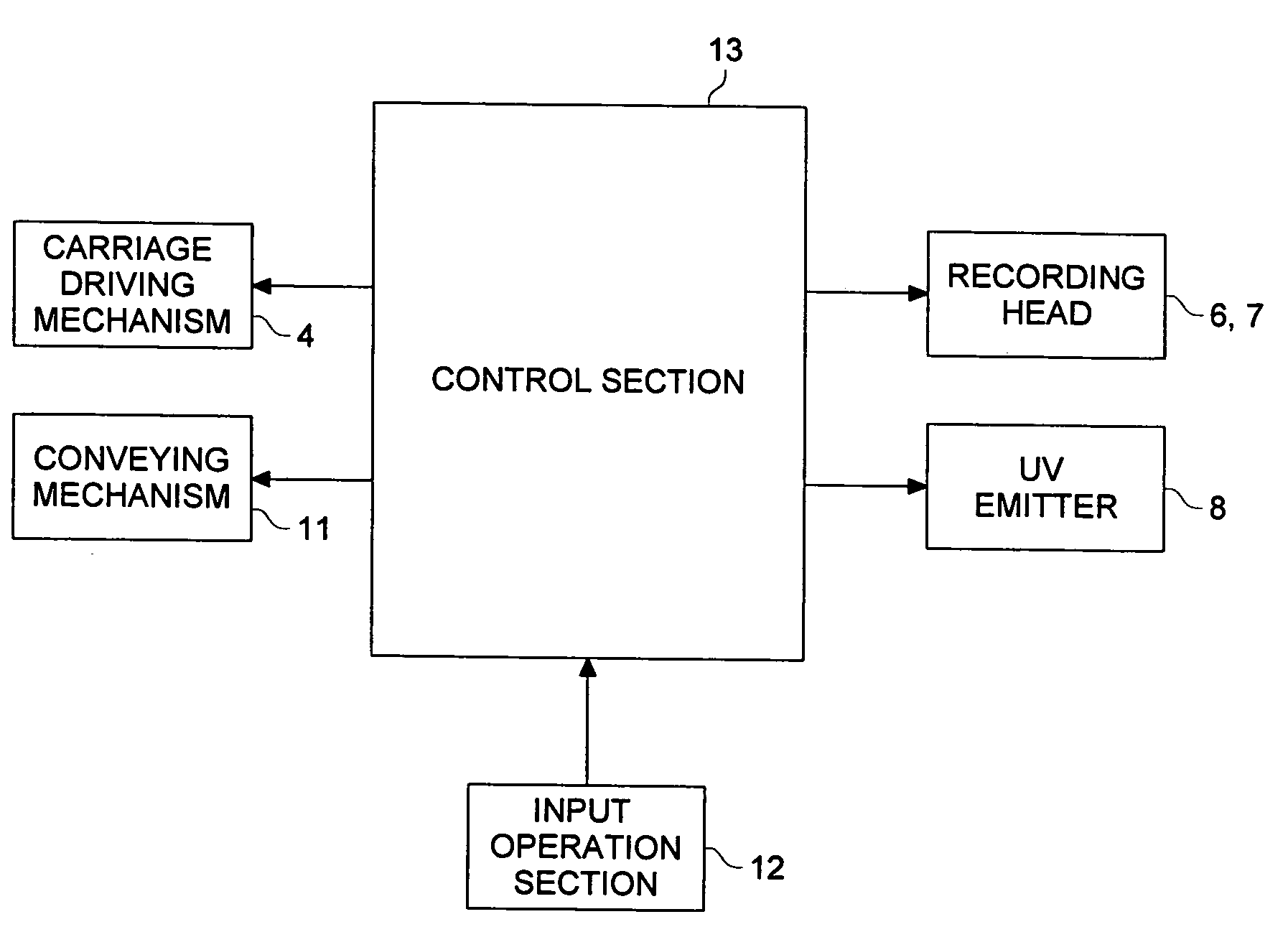
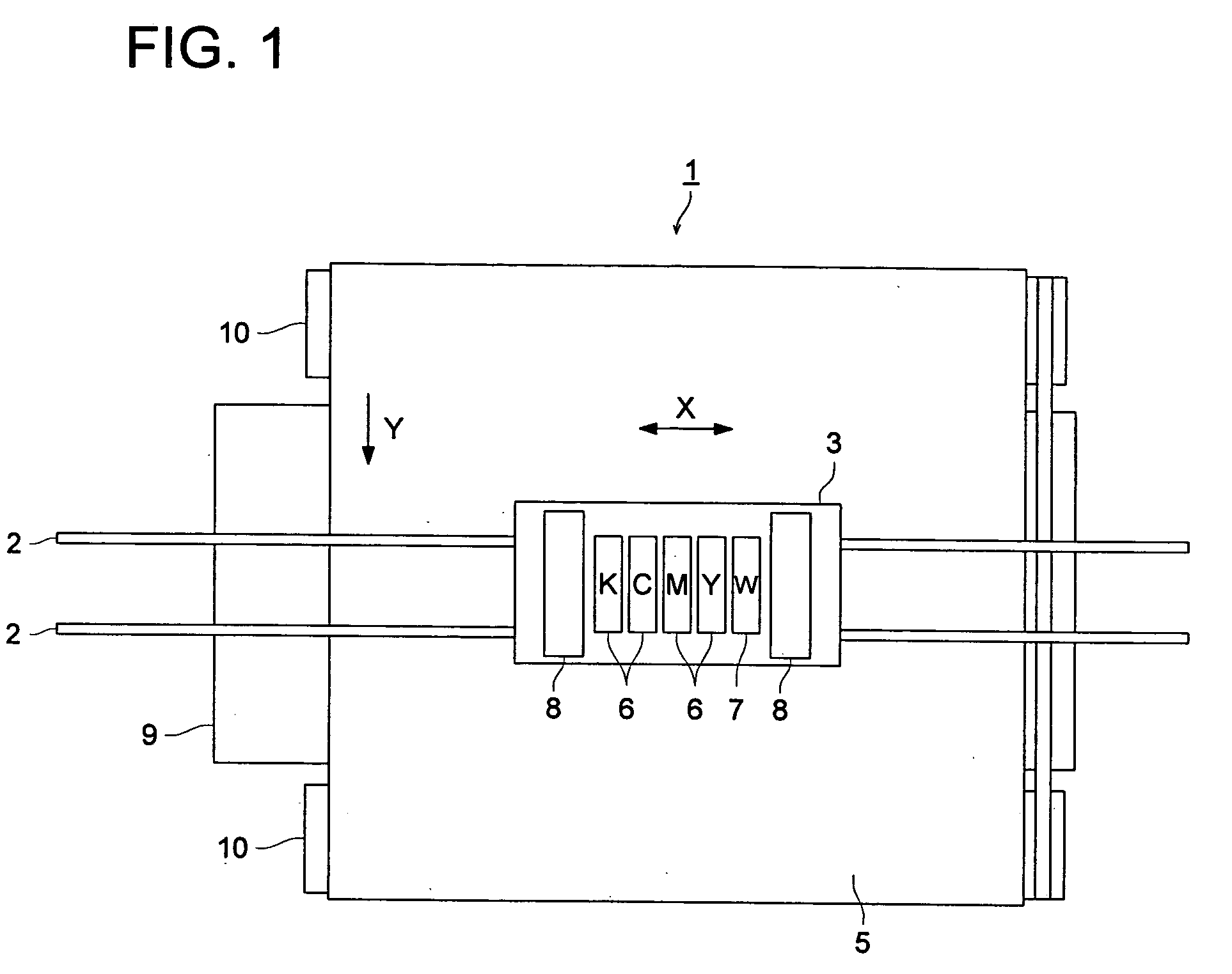
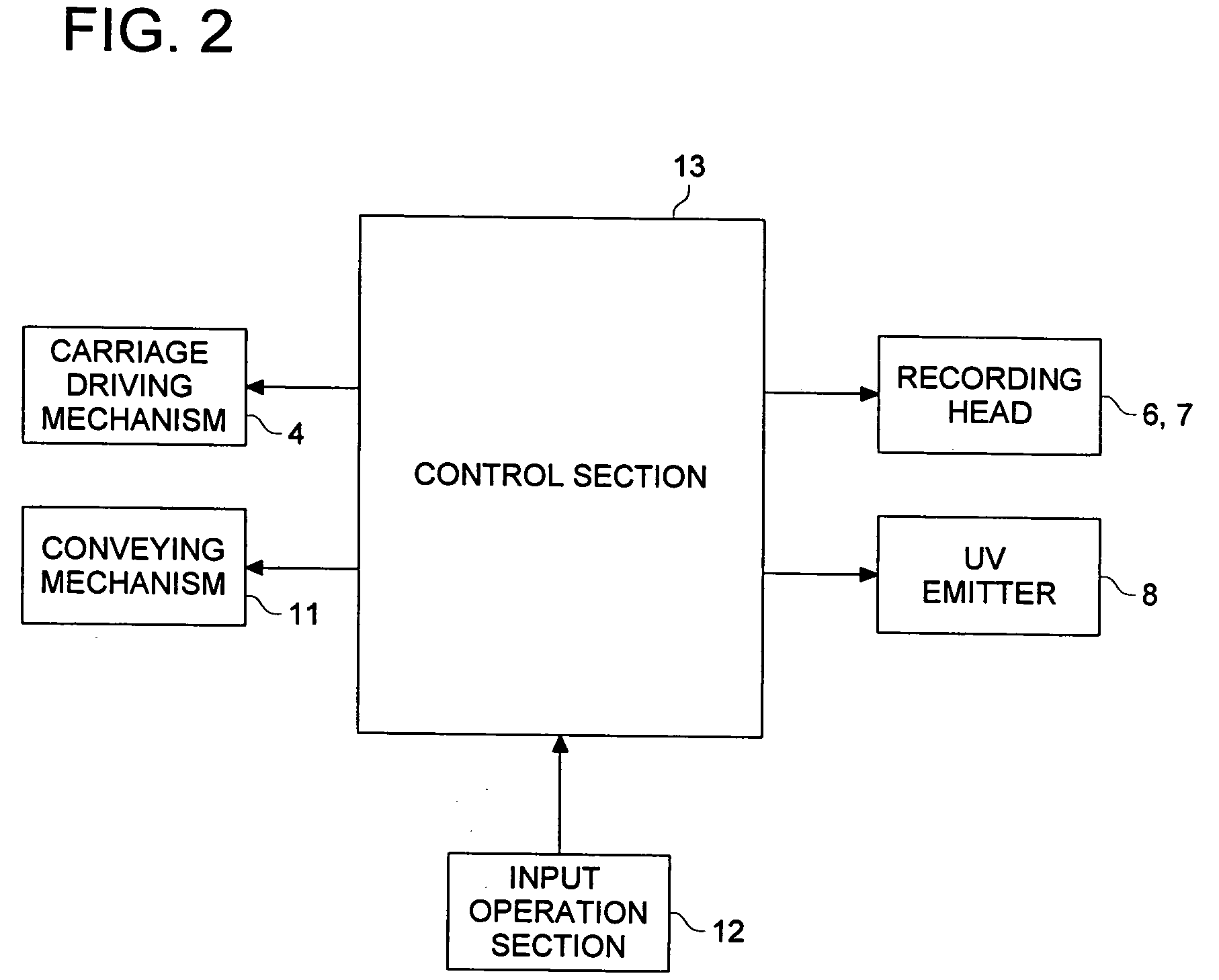
[0023]FIG. 1 shows an inkjet recording apparatus 1 of a serial head type in an embodiment in accordance with the invention. The inkjet recording apparatus 1 includes, as shown in FIG. 1, guide rails 2 in the shape of bars which support a carriage 3. The carriage 3 is reciprocally moved by a carriage driving mechanism 4 (see FIG. 2) along the guide rails 2 in sub scanning direction X.
[0024] In the central part of the carriage 3, there are mounted image recording heads 6 formed with nozzles for jetting inks as image recording inks, for mostly recording an image, in respective colors of yellow (Y), magenta (M), cyan (C), and black (K), and there is also mounted an auxiliary recording head 7, for enhancement of image recording, formed with nozzles for jetting white ink (W) for recording a solid white background of the image recorded with the image recording inks, the r...
PUM
 Abstract
Description
Claims
Application Information