Plasma television, display panel type television, and fabrication method for display panel type television

a technology of display panel and television, which is applied in the direction of television system, identification means, instruments, etc., can solve the problems of unfavorable production and production of plasma display panels, and inability of workers to fasten all screws evenly, so as to prevent distortion of frame members or unnecessary loads, the effect of preventing distortion of frame members

Inactive Publication Date: 2005-10-27
FUNAI ELECTRIC CO LTD
View PDF3 Cites 18 Cited by
  • Summary
  • Abstract
  • Description
  • Claims
  • Application Information

AI Technical Summary

Benefits of technology

[0046] As described above, according to the present invention it is possible to provide the plasma television that prevents distortions in the frame member of unnecessary loads on the plasma display panel or optical filter, and to allow maintaining required parallelism between the optical filter and the panel type display apparatus.
[0047] This wi

Problems solved by technology

However, the worker is not always able to fasten all the screws evenly.
Unless all the screws are fastened evenly, it is difficult to keep the glass substrate optical filter and a plasma display panel 8 in parallel.

Method used


Image

  • Plasma television, display panel type television, and fabrication method for display panel type television
  • Plasma television, display panel type television, and fabrication method for display panel type television
  • Plasma television, display panel type television, and fabrication method for display panel type television

Examples


Embodiment Construction

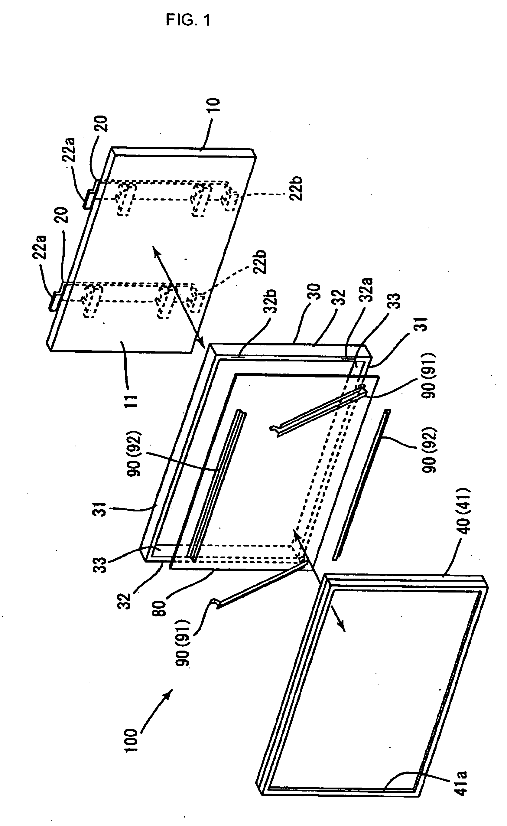
[0055]FIG. 1 is a perspective exploded view of a plasma television according to the present invention.

[0056] Although the television fabrication method according to the present invention can be used for any flat panel television including an LCD television, fabrication of a plasma television will be described as an example in this embodiment.

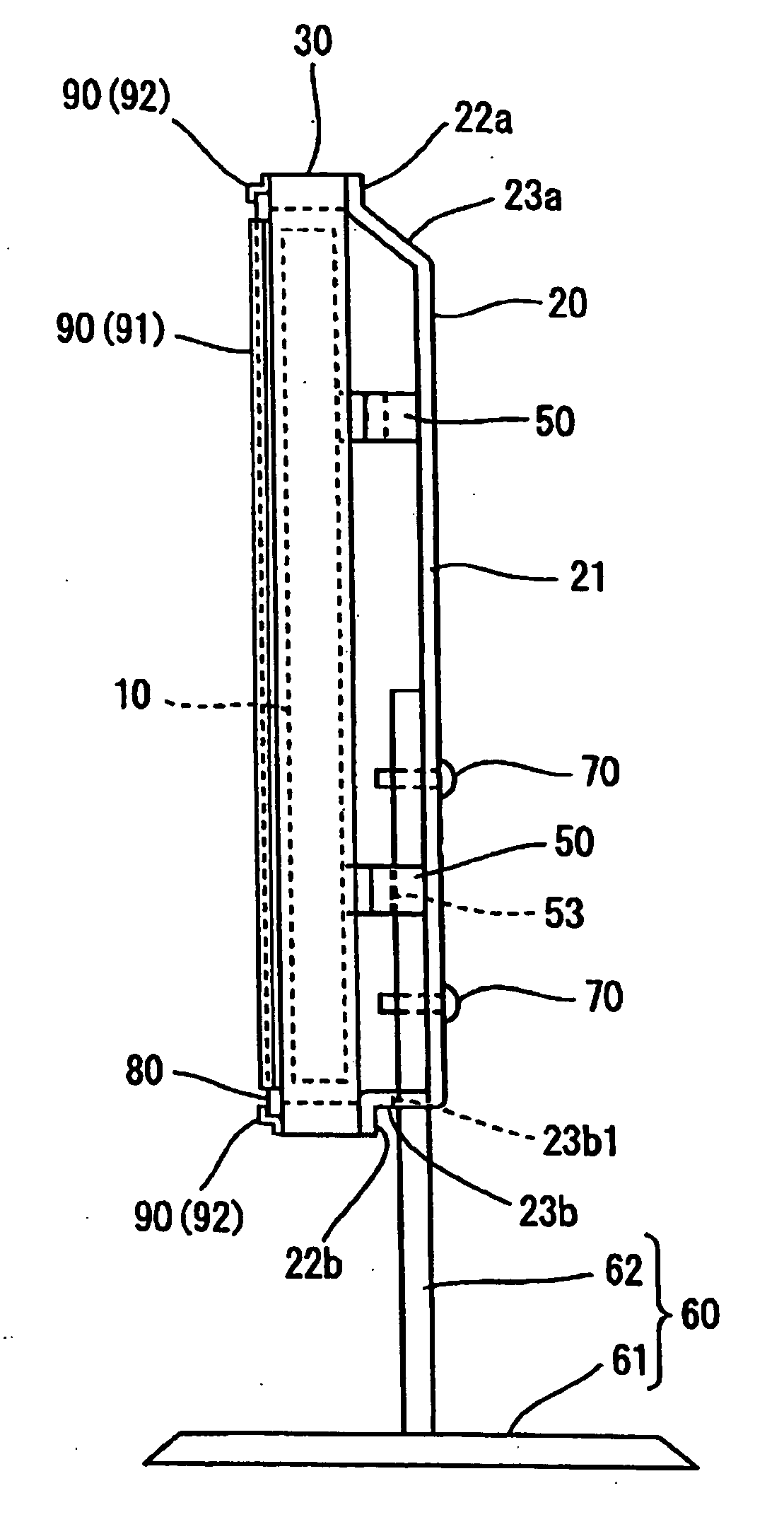
[0057] As shown in FIG. 1, a plasma television 100 basically consists of a plasma display panel (PDP) 10, a frame 30, an optical filter 80, and a casing 40. The casing 40 comprises a front casing 41 and a rear casing, but the rear casing is not shown here. An opening 41a is formed around the center of the front of the front casing 41, and the PDP 10 is disposed within the casing 40 with its front display surface facing said opening 41a.

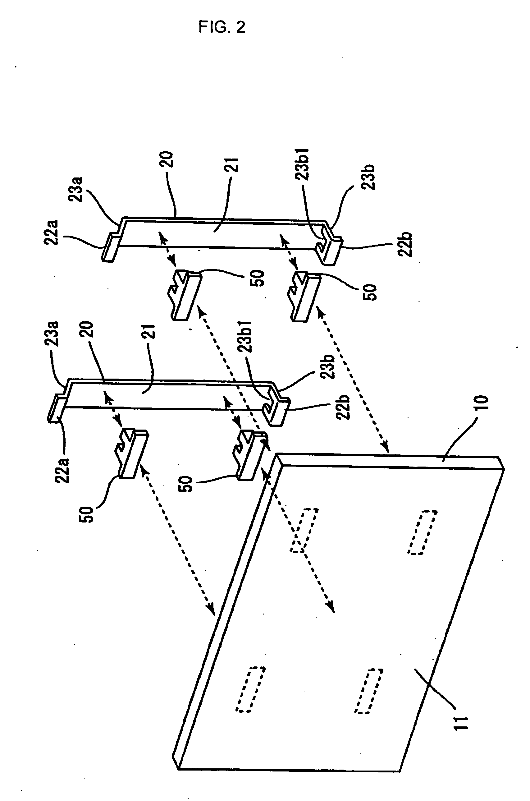
[0058] In this embodiment, first, the PDP 10 is fixed to brackets 20; the method of fixing the PDP 10 to the brackets 20 will be described later. Next, the brackets 20 supporting the PDP 10 are fixed to a frame...


PUM


Abstract

Conventionally, it was difficult to maintain parallelism between an optical filter and a PDP, and also the weight of the optical filter was put on the PDP.
With a PDP 10 and a frame 30 separately fixed to a bracket 20 connecting to a leg member 60, fix an optical filter 80 to the frame 30. As a result, the optical filter 80 is fixed with required parallelism maintained with the PDP 10, and also the optical filter 80 and the PDP 10 will not put their weight on each other, thus eliminating unnecessary loads on the optical filter 80 and the PDP 10. Also, unnecessary flaws and distortions in a casing 40 can be prevented during the product manufacturing.

Description

BACKGROUND OF THE INVENTION [0001] 1. Field of the Invention [0002] The present invention relates to a plasma television, a display panel type television, and a fabrication method of the display panel type television. [0003] 2. Description of the Prior Art [0004] As a related prior art, there is known a plasma display apparatus wherein a glass substrate optical filter 5 is fixed on the front side of a front frame 3 (refer to the Japanese Patent Laid-Open No. 2003-5669, for example). [0005] In this apparatus, after a plasma display panel 8 and a back cover 6 are installed with screws 9, the glass substrate optical filter 5 is slid into a groove on a hook-shaped projection 4 and temporarily fixe on the front side of the front frame 3. Then, the four corners of the glass substrate optical filter is pressed with pressure fixtures 2 and secured on the front side of the front frame with screws 7. Then, a front side outer case is overlaid on the glass substrate optical filter. [0006] In th...

Claims


Application Information

Patent Timeline
IPC IPC(8): H04N5/65G06F1/16G09F9/00H04N3/12H04N5/64
CPCG06F1/1601H04N5/64G06F2200/1612
Inventor MARUTA, NAOTO
Owner FUNAI ELECTRIC CO LTD
Why Eureka
Try Eureka