
Method for selecting a golf putter

a golf putter and golf technology, applied in golf clubs, golf accessories, racket sports, etc., can solve the problems of increasing the tension in the player's hands and arms, increasing increasing the difficulty of aiming the putt, so as to reduce the negative effect of the ball direction, optimize the radius, and reduce the effect of negative effects

Inactive Publication Date: 2005-10-27
POLLMAN FREDERIC W
View PDF4 Cites 0 Cited by
  • Summary
  • Abstract
  • Description
  • Claims
  • Application Information

AI Technical Summary

Benefits of technology

The putter improves stance alignment, reduces mis-hit effects, and enhances ball direction control, allowing players of various skill levels to hole the ball more efficiently while minimizing muscle tension and putter rotation during strokes.

Problems solved by technology

A further disadvantage of this longitudinal location of the shaft is to place the ball back in the stance, making aiming a putt more difficult.
However, the shaft is close to the strike face, still keeping the ball undesirably forward in the stance.
This increases tension in the player's hands and arms.
However, this putter cannot be made in one piece, which increases cost.
None of these patents disclose how the center of gravity should be located with respect to the player and the pivot point of the swing, and none show inertia weighting that meets cost and dimensional requirements.
This patent does not disclose any relationship to a player's stance and does not have a small enough transverse radius to allow for an ideal stance for some players.
U.S. Pat. No. 6,406,379—Christensen (2002) has a smaller transverse radius, but its value is too large to optimize the hitting area when the putter is tipped transversely.
It has an alignment stripe that has a small length to width ratio making it difficult to establish directionality, and the color is not specified.
The sighting surface in Klein '941 is also in three sections making it difficult to focus on that surface.
These current putters do not align the grip flat with any particular portion of a player's hand to allow accurate rotational orientation of the putter.

Method used


Image

  • Method for selecting a golf putter
  • Method for selecting a golf putter
  • Method for selecting a golf putter

Examples


Embodiment Construction

A Player's Stance and Aim.

[0029] When putting a golf ball, a proper stance is necessary preparation for striking the ball. It is generally agreed by experts that the eyes of the player should be vertically over the aimline in order to provide the most accurate vision of it, and that alignment of the player's feet with the aimline is necessary for consistent stroking of the putter. Many experts counsel minimum muscle use during stroking of a putter in order to minimize errors. For many players, having the eyes over the aimline and using minimum muscles leads to an upright stance with the arms hanging loosely and the legs and back muscles supporting minimum overhung weight. Further, it is easier to align two objects, such as the ball and the aimline, from a single direction rather than to look backward and forward. Aligning the ball and the aimline from one direction leads to a stance that places the player's eyes behind the ball. Consistent orientation of the putter in the player's h...


PUM


Abstract

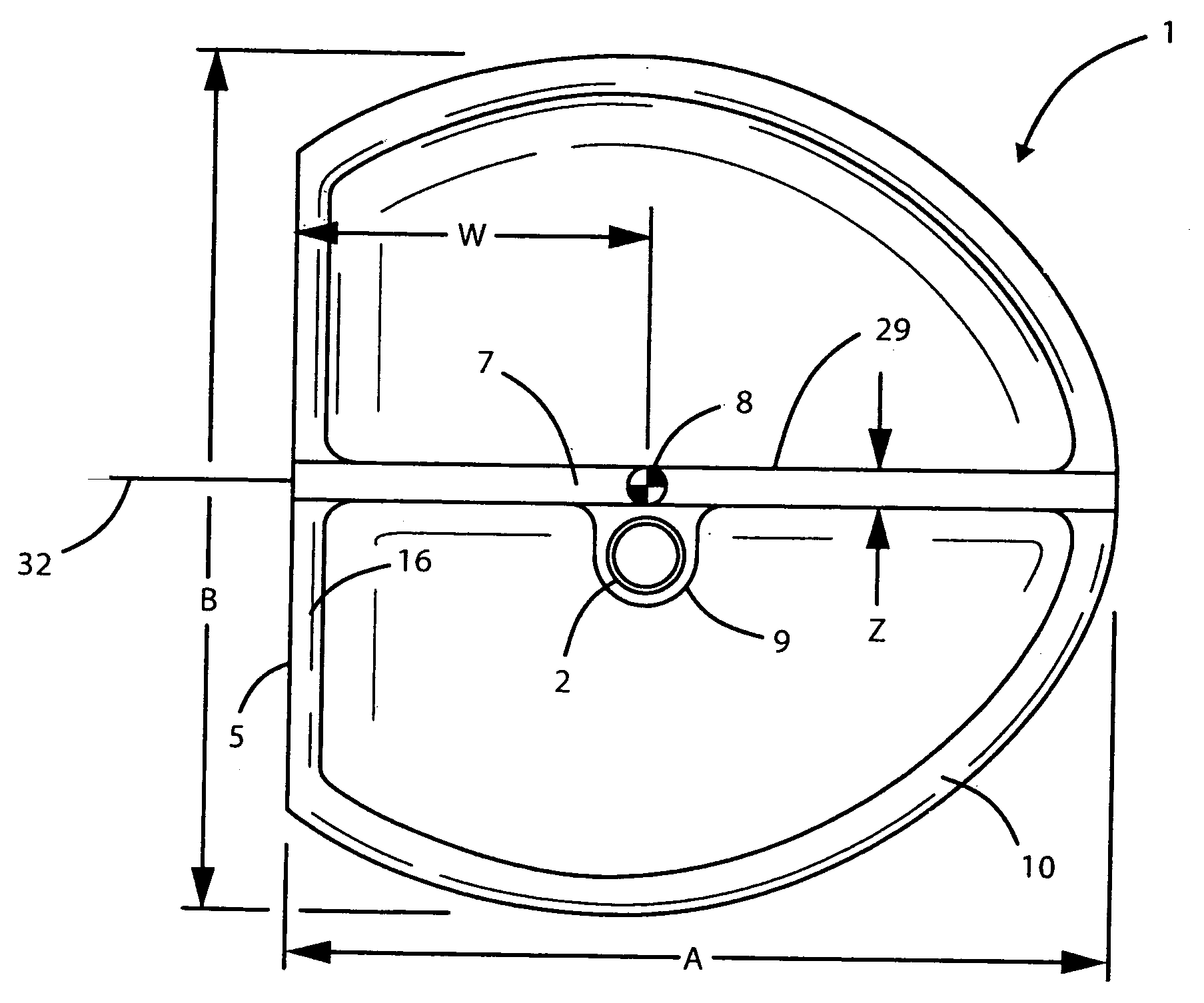
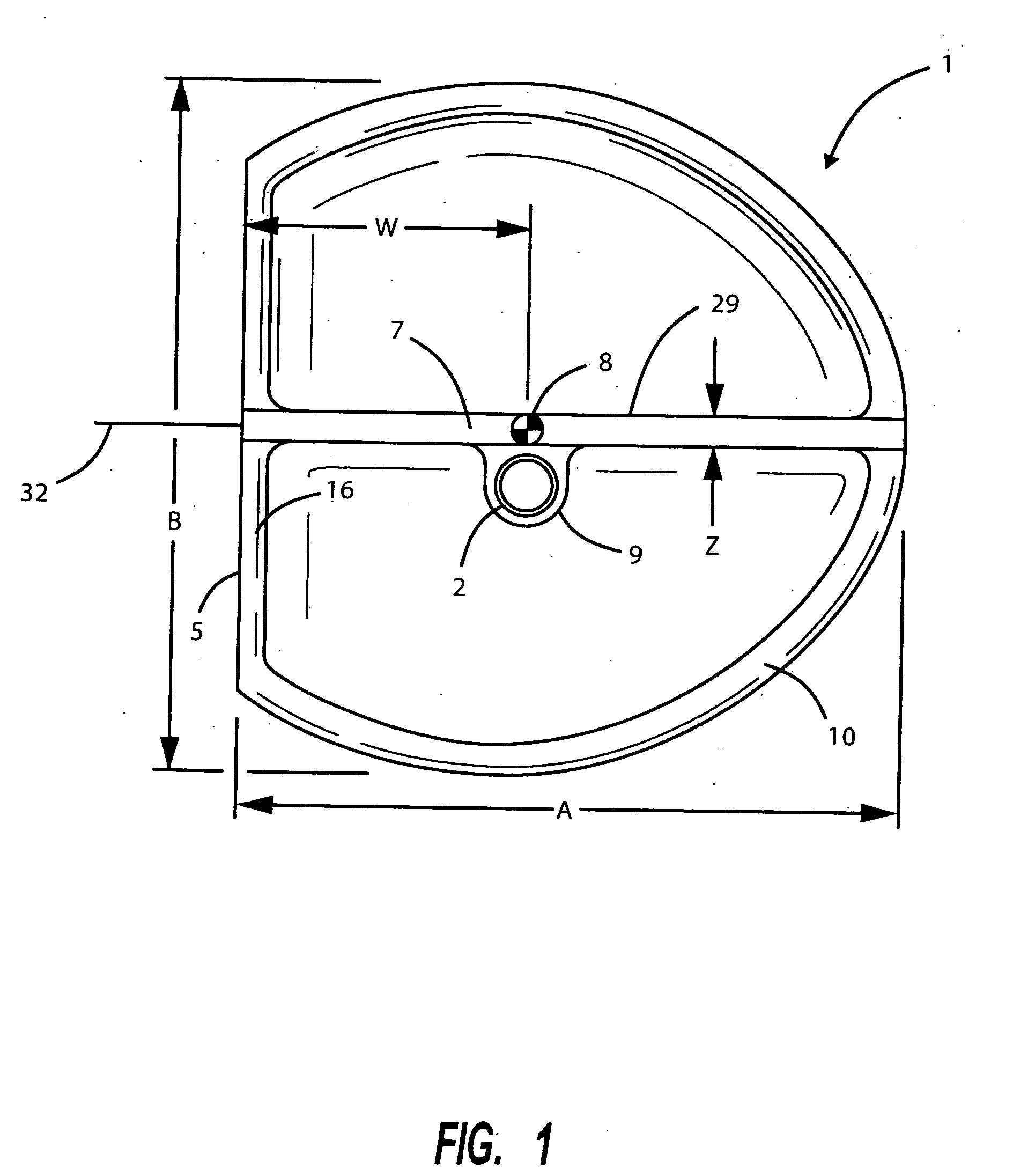
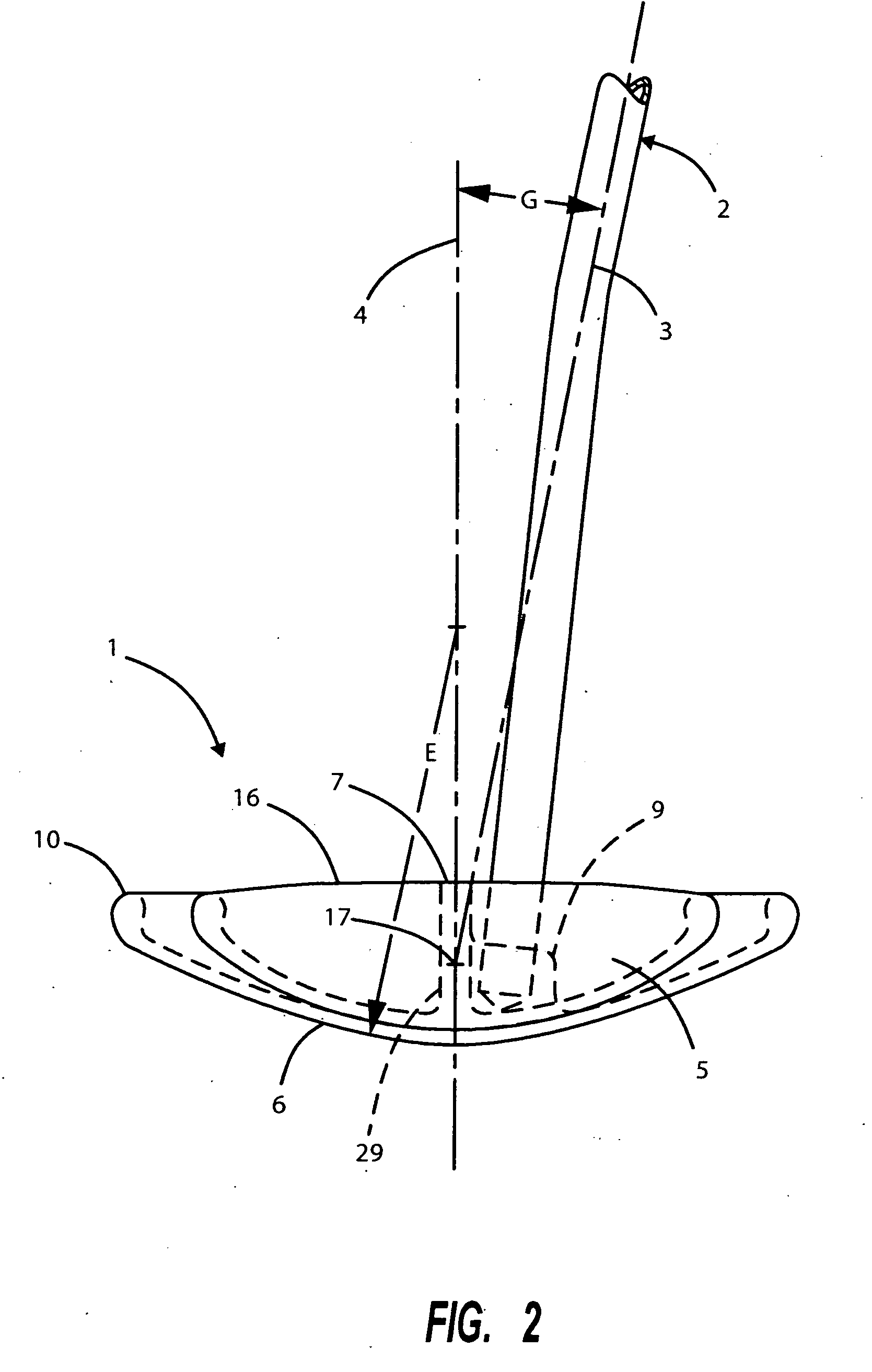
A putter has a center of gravity located rearward from the face and under the stroking pivot point. The polar moment of inertia of the putter is increased by moving the distribution of weight toward the rear of the head away from the contact surface. The sole of the putter has an optimized transverse radius and a raised front edge. The putter has an aiming mark that has a minimum area and a minimum length-to-width ratio and is brightly colored. The putter grip has a flat portion that is oriented to match the player's hand rotational position. The face of the putter has friction and energy transfer characteristics that are selected to influence ball motion if struck with stroking errors. The face loft angle cooperates with the face surface characteristics to influence ball launch angle and rotation.

Description

BACKGROUND OF THE INVENTION [0001] This invention generally relates to golf clubs and specifically to clubs for putting a golf ball into a hole. [0002] Publications providing specifications, instruction and other data in the field of putting include “The Rules of Golf” from the United States Golf Association (2002), “Dave Pelz's Putting Bible” from Doubleday (2000), and “The Ultimate Clubmakers Catalog” from Golfsmith International, LP (2003). [0003] Putting is a major component of scoring in the game of golf, often comprising about 40% of the strokes used. Putting is a precise activity with a very low error required for holing most putts. As putting requires low force but high accuracy, improvements for putters have greatest potential in facilitating a good stance and proper aim, and consistent stroking of the putter. The degree of achieving these requirements will vary with the skill level of the player as well as with playing conditions. [0004] The putter disclosed herein has a w...

Claims


Application Information

Patent Timeline
Patent Type & Authority Applications(United States)
IPC IPC(8): A63B53/02A63B53/04A63B59/00
CPCA63B53/02A63B53/0487A63B2225/01A63B2053/0441A63B2059/0007A63B2053/0416A63B53/0416A63B53/0441A63B60/004
Inventor POLLMAN, FREDERIC W.
Owner POLLMAN FREDERIC W
Learn More