Method of sharing state between stateful inspection firewalls on MEP network

Inactive Publication Date: 2005-10-27
SEOUL NAT UNIV R&DB FOUND
View PDF2 Cites 126 Cited by
  • Summary
  • Abstract
  • Description
  • Claims
  • Application Information

AI Technical Summary

Problems solved by technology

However, the conventional stateful inspection firewall is problematic in that it is only available on a network having a single entry point because all the incoming and outgoing traffics of a connection must be monitored to keep track of the connection state t6.
That is, the conventional stateful

Method used


Image

  • Method of sharing state between stateful inspection firewalls on MEP network
  • Method of sharing state between stateful inspection firewalls on MEP network
  • Method of sharing state between stateful inspection firewalls on MEP network

Examples


Embodiment Construction

[0026] Reference now should be made to the drawings, in which the same reference numerals are used throughout the different drawings to designate the same or similar components.

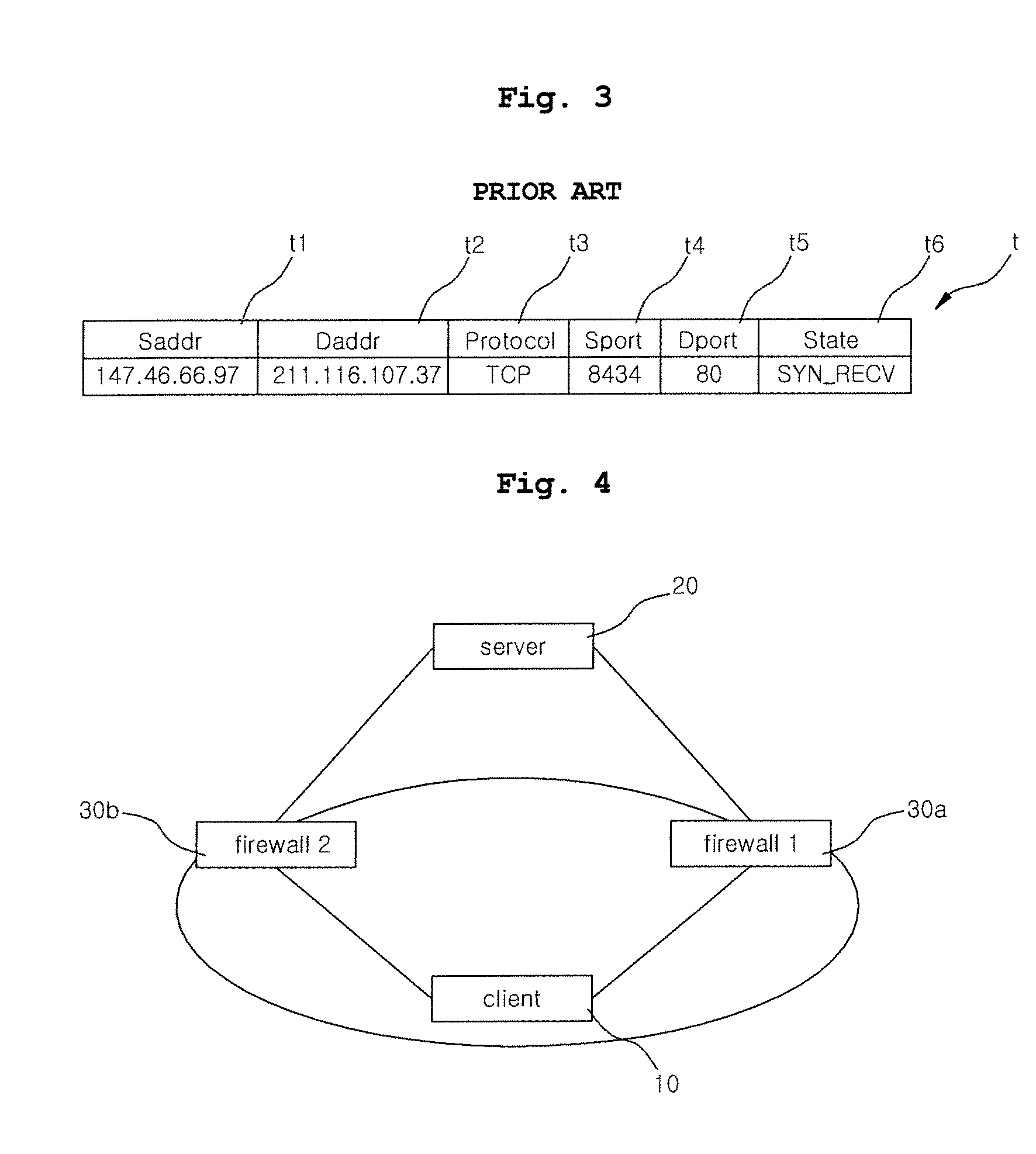
[0027]FIG. 4 is a system configuration diagram illustrating a method of sharing a state between stateful inspection firewalls on an MEP network in accordance with the present invention.

[0028] The MEP network, as shown in FIG. 4, includes a client 10, a server 20, and a firewall 130a and a firewall 230b that are physically remote from each other. In this case, the firewall 130a and the firewall 230b are installed to protect the network of the client 10 from the outside thereof. The firewall 130a and the firewall 230b are stateful inspection firewalls 30, which intercept exchanged packets, extract connection information from the intercepted packets, update internal state tables t, and make the determination of filtering based on the updated state tables t.

[0029]FIG. 4 depicts only a preferred embodiment of t...


PUM


Abstract

The present invention is devised to solve the problem in which a state cannot be kept track of because an outgoing traffic and an incoming traffic pass through different firewalls on a Multiple Entry/Exit Point (MEP) network having a plurality of entry points. In the present invention, firewalls physically remote from each other can share connection information using a modified SYN cookie, so that stateful inspection firewalls physically remote from each other can be used even on the MEP network.

Description

BACKGROUND OF INVENTION [0001] 1. Field of the Invention [0002] The present invention relates generally to a method of sharing a state between stateful inspection firewalls on a multiple entry / exit point network and, more particularly, to a method of sharing a state between stateful inspection firewalls on a multiple entry / exit point network, which enables the state to be shared between the stateful inspection firewalls using a modified SYN cookie on the multiple entry / exit point network having a plurality of access points physically remote from each other. [0003] 2. Description of the Related Art [0004] In general, a firewall is located at the boundary of a network, and functions to protect the network from the outside thereof. Recently, of various firewalls, a stateful inspection firewall is widely used. The stateful inspection firewall performs the function of a firewall in such a way as to intercept an incoming or outgoing packet, extract connection information, such as the sour...

Claims


Application Information

Patent Timeline
IPC IPC(8): H04L9/00H04L29/06
CPCH04L63/0254
Inventor KIM, JIN-HOBAHK, SAE-WOONGLEE, HEE-JO
Owner SEOUL NAT UNIV R&DB FOUND
Why Eureka
Try Eureka