
Asymmetric retaining wall block

a technology of retaining walls and blocks, applied in the field of walls, can solve the problems of not being able to subdivide such blocks, certain types of constructions are possible, and the construction of retaining walls is labor-intensive, and achieve the effect of facilitating the splitting of blocks

Inactive Publication Date: 2005-11-03
MORTARLESS TECH
View PDF31 Cites 21 Cited by
  • Summary
  • Abstract
  • Description
  • Claims
  • Application Information

AI Technical Summary

Benefits of technology

[0005] A masonry block that can be used to construct retaining walls and free standing walls is disclosed. The block is distinguished by a weakened section that serves the dual purposes of permitting the block to be readily split into two block segments and presenting the appearance of tow adjacent blocks. A preferred embodiment of the block comprises spaced apart top and bottom surfaces defining the height of the block; a front surface extending in a direction between the top and bottom surfaces; a rear surface spaced from the front surface by a distance defining the depth of the block; a first side surface located between the top and bottom surfaces and between the front and rear surfaces; a second side surface spaced from the first side surface, the second side surface located between the top and bottom surfaces and between the front and rear surfaces; the block further comprising a weakened section located between the front and the rear surfaces, the weakened section configured and arranged to facilitate splitting the block from either one of the front or rear surfaces; and, a first groove in the front surface extending vertically between the top and bottom surfaces, whereby the first groove may serve to assist in splitting the block and also presents a front surface simulating two separate blocks.

Problems solved by technology

In the past, retaining wall construction was labor intensive and often required the skills of trained trades people such as masons and carpenters.
However, a drawback with such channels is that they are usually clearly identifiable as such, especially when compared to vertical joints that are formed between adjacent blocks.
Another drawback with such blocks, is that only certain types of constructions are possible, such as vertically aligned walls or walls that may be rearwardly offset.
Such prior art blocks are usually not available in different sizes nor is it possible to subdivide such blocks with consistent results.

Method used


Image

  • Asymmetric retaining wall block
  • Asymmetric retaining wall block
  • Asymmetric retaining wall block

Examples


Embodiment Construction

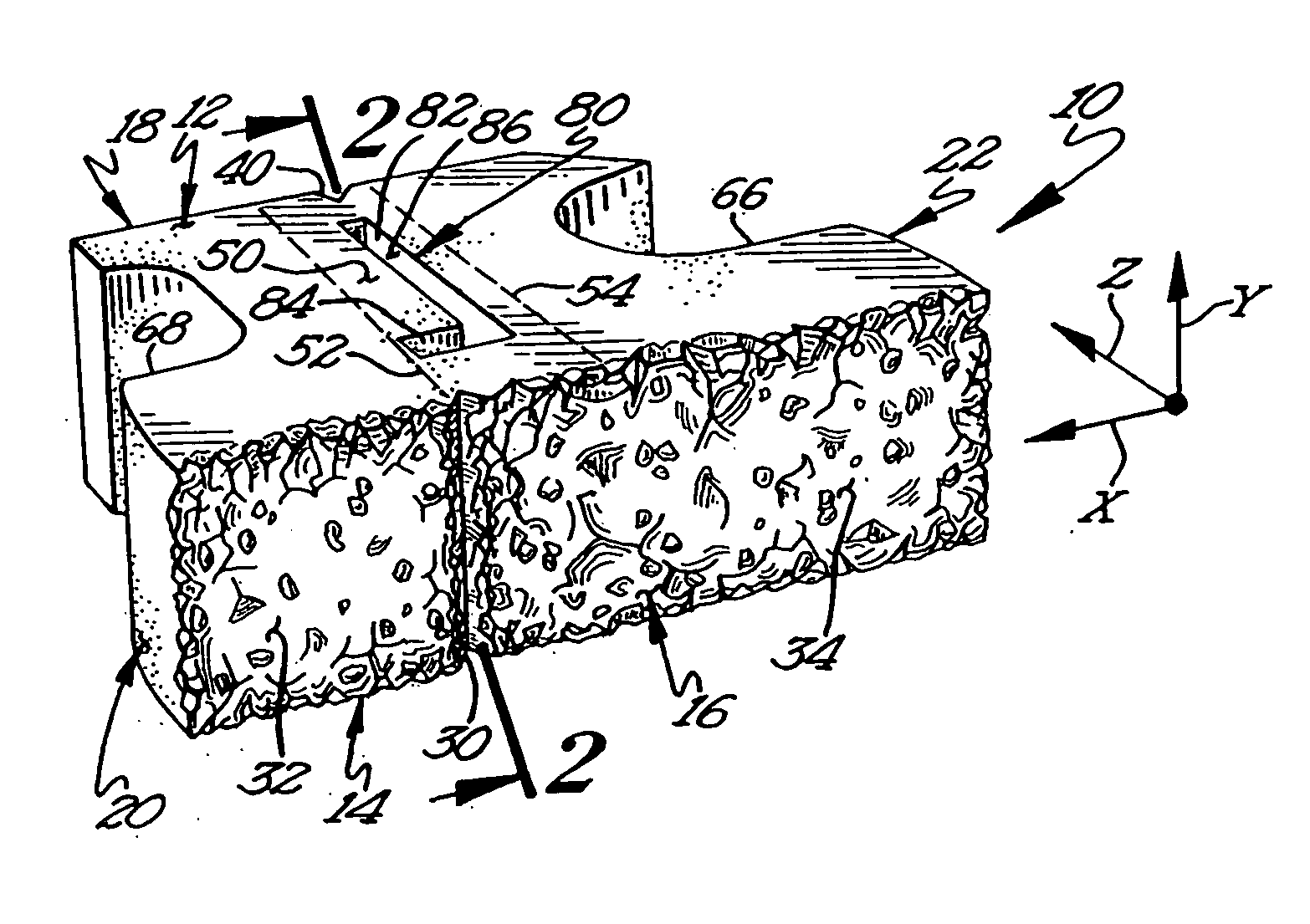
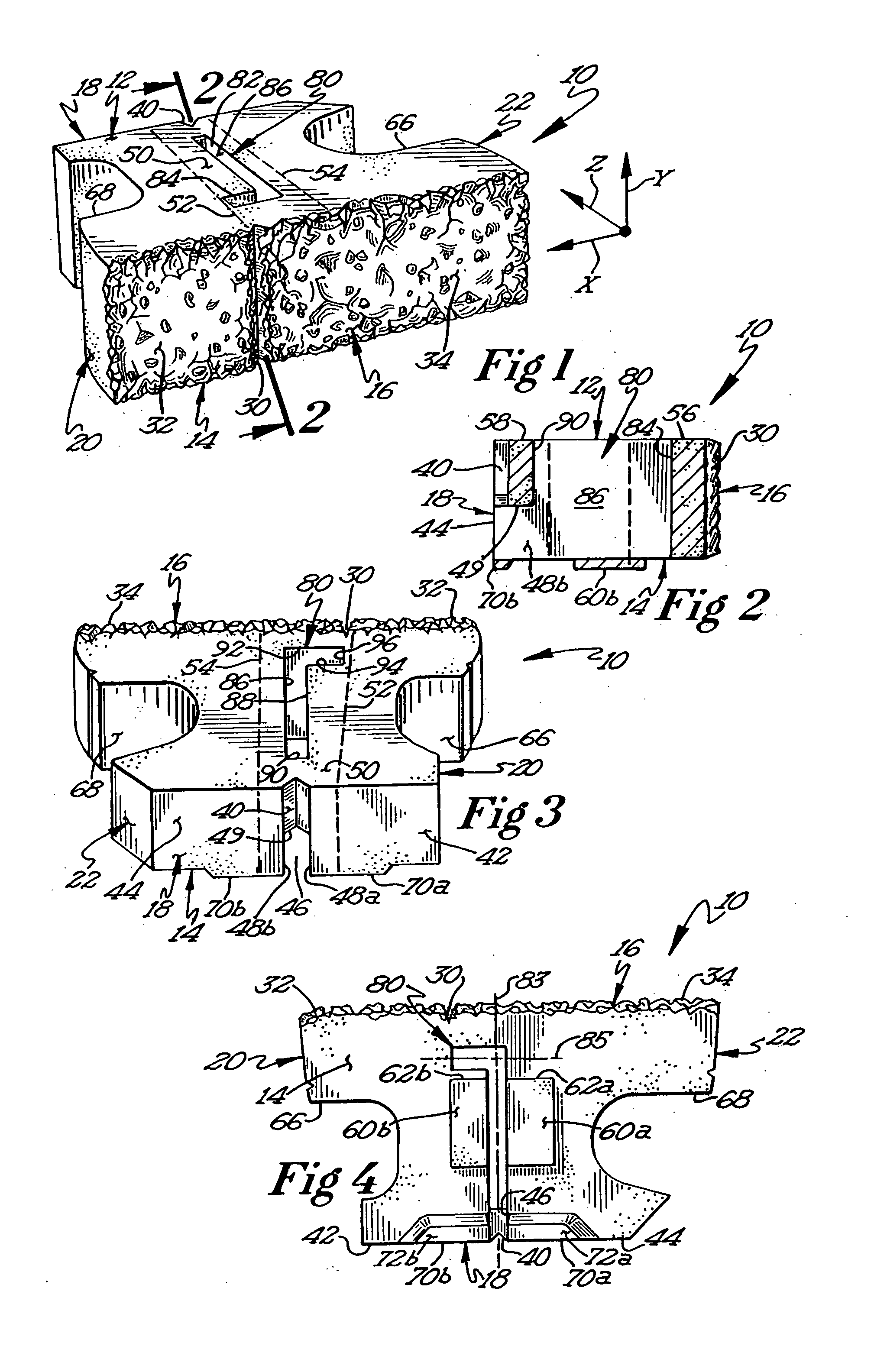
[0026] Turning to the figures wherein like parts are designated with like numerals throughout several views, the directions vertical and horizontal as used herein are made with reference to blocks in their normal position of use, eg. as in a wall, and wherein the dimensions of height, width, and depth correspond to the x, y, and z axes in a three dimensional coordinate system. With reference to FIG. 1 a preferred embodiment of a wall block 10 comprising a top surface 12, a bottom surface 14, a front surface 16, a rear surface 18 (see, FIGS. 2, 3, and 4), and first and second side surfaces 20, 22, respectively, is disclosed. The front surface 16, as depicted, includes a first groove 30 that extends vertically between the top and bottom surfaces, 12 and 14. The first groove 30 simulates a joint that is normally formed between the sides of adjacent blocks in a course of blocks. In forming the simulated joint, the first groove 30 divides the front surface or facing into two panels 32 an...


PUM

PropertyMeasurementUnit
distanceaaaaaaaaaa
distanceaaaaaaaaaa
distanceaaaaaaaaaa

Abstract

A block suitable for use in a retaining wall, the block has a top surface, a bottom surface, a front surface, a rear surface, and opposed sides. The block includes a weakened section that extends substantially from the front to the rear surface, and which is configured and arranged to facilitate splitting the block into two smaller blocks. The weakened section can take the form of one or more slots that are generally situated within the body of the block and one or more grooves located at the front and rear surfaces, respectively. The groove at the front surface of the block is configured and arranged to simulate a joint between two adjacent blocks. Preferably, the front groove is formed by a core that modifies the block as it is removed from the mold in which it was cast. The block may include one or more projections and / or positioning elements that extend from the block in a generally vertical direction, and which are configured and arranged to engage a block in an adjacent course of blocks.

Description

FIELD OF THE INVENTION [0001] This invention relates generally to the construction of walls used in landscaping applications. More particularly, the present invention relates to a masonry block that can be used to build retaining walls. BACKGROUND OF THE INVENTION [0002] Retaining walls are widely used in a variety of landscaping applications. Typically, they are used to maximize or create level areas and to reduce erosion and slumping. They may also be used in a purely decorative manner. In the past, retaining wall construction was labor intensive and often required the skills of trained trades people such as masons and carpenters. More recently, retaining wall construction has become significantly simplified with the introduction of self-aligning, modular, molded blocks of concrete that may be stacked in courses without the use of mortar or extensive training. With these types of blocks, it is possible to erect a retaining wall quickly and economically, and the finished product cr...

Claims


Application Information

Patent Timeline
Patent Type & Authority Applications(United States)
IPC IPC(8): B28B7/00B28B17/00E02D29/02E04B1/00E04B2/02E04C1/39
CPCB28B7/0061B28B17/0018E04C1/395E04B2002/026E02D29/025
Inventor PRICE, RAYMOND R.
Owner MORTARLESS TECH
Features
  • Generate Ideas
  • Intellectual Property
  • Life Sciences
  • Materials
  • Tech Scout
  • Unparalleled Data Quality
  • Higher Quality Content
  • 60% Fewer Hallucinations
Learn More