Touch Screen Displays

a touch screen display and touch screen technology, applied in instruments, climate sustainability, computing, etc., can solve the problems of data connection and power requirements that are relatively inefficient both in terms of data connections and power requirements, and achieve the effect of improving user experien

Inactive Publication Date: 2012-12-06
FLEXENABLE LTD
View PDF9 Cites 31 Cited by
  • Summary
  • Abstract
  • Description
  • Claims
  • Application Information

AI Technical Summary

Benefits of technology

[0012]In preferred embodiments, therefore, the display screen is segmented so that as well as the row and column electrodes only going approximately half way across the display screen from either side, all the ends of the electrodes at each side of the display screen go into respective first, second, third and fourth touch sensing circuit modules (or integrated circuits). Then the pair of (interpolating) Y-position (row) sensing modules can be employed to determine which column sensing module is to be employed to determine the X-(column) position, by identifying whether the touch row is towards one or the other end of a column, and hence toward one or the other of the X-(column) sensing modules. In a corresponding way the (interpolating) output from the column sensing modules can be used to determine which of the row sensing modules to employ when sensing (interpolator) Y-position. Further, in preferred embodiments employing one touch sensing integrating circuits to perform the function of each touch sensing circuit module enables these integrated circuits (ICs) each to be located physically adjacent one side (or edge) of the display screen, close to the connections to the relevant ends of the row and column electrode lines, thus reducing the distance over which interconnects need travel and minimising external noise. In preferred embodiments each of these touch sensing circuit modules or ICs has a serial data output, for example a SPI (Serial Peripheral Interface) bus or I2C (Inter-Integrated circuit) bus.
[0014]In preferred embodiments the controller microprocessor also identifies gestures and / or geometrical objects such as lines or circles which are primitives for gestures and outputs corresponding object and / or gesture data in preferred embodiments the controller microprocessor also outputs the row and column interpolated position data as well as the higher level data in order to enable corresponding image data to be written back to the display either as an indication on the display of where the display was touched or in the form of an icon or other response to an interpreted gesture, or both. This approach facilitates, for example, a combination of gesture recognition and user annotation of a document on an electronic document reader since having the row and column interpolated position data available in addition to gesture recognition data enables such annotation as well as reducing overall data flow and facilitating division of different types of processing task between the controller and a higher level, main processor.
[0017]In embodiments the main processor performs a cold boot in response to the power supply to the main processor being turned on, prior to performing the desired action. For this reason in embodiments only a selected portion of the operating system of the main processor is loaded, that needed to perform the desired action, in order that the processor starts up quickly to enhance the user experience.

Problems solved by technology

In theory it would be possible to segment the display screen into quadrants and to apply one touch sensing circuit module or integrated circuit to form touch sensing for each quadrant, but this would create problems at the boundaries of the quadrants, in particular when interpolating touch sensed position between electrode lines.
However this is a relatively inefficient both in terms of data connections and power requirements.

Method used


Image

  • Touch Screen Displays
  • Touch Screen Displays
  • Touch Screen Displays

Examples


Embodiment Construction

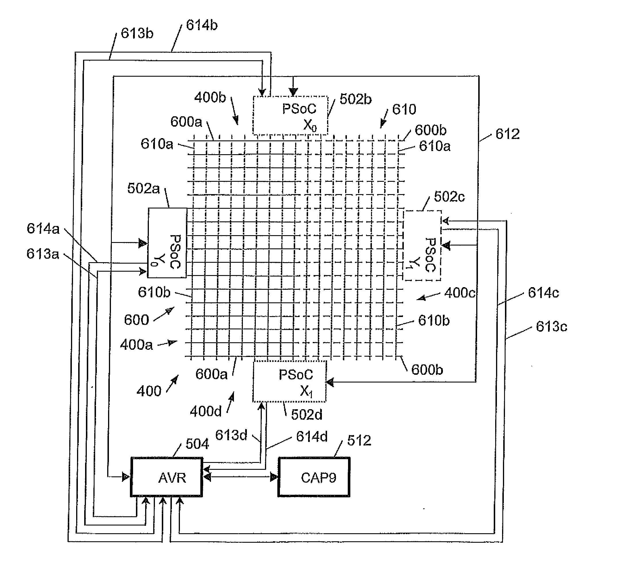
[0027]The present inventions relate to improved techniques for implementing touch screen displays, in particular projected capacitance touch screen sensing for large electrophoretic display screens, and to electronic document readers implementing these techniques.

[0028]We first describe an example of an electronic document reading device, to illustrate the context in which embodiments of the invention may be employed. Embodiments of the invention can be especially useful for large screen devices, in particular devices with large, flexible electrophoretic display screens as described further below. However applications of embodiments of the invention are not limited to such devices and also include, for example, a device with an LCD display screen on a glass substrate.

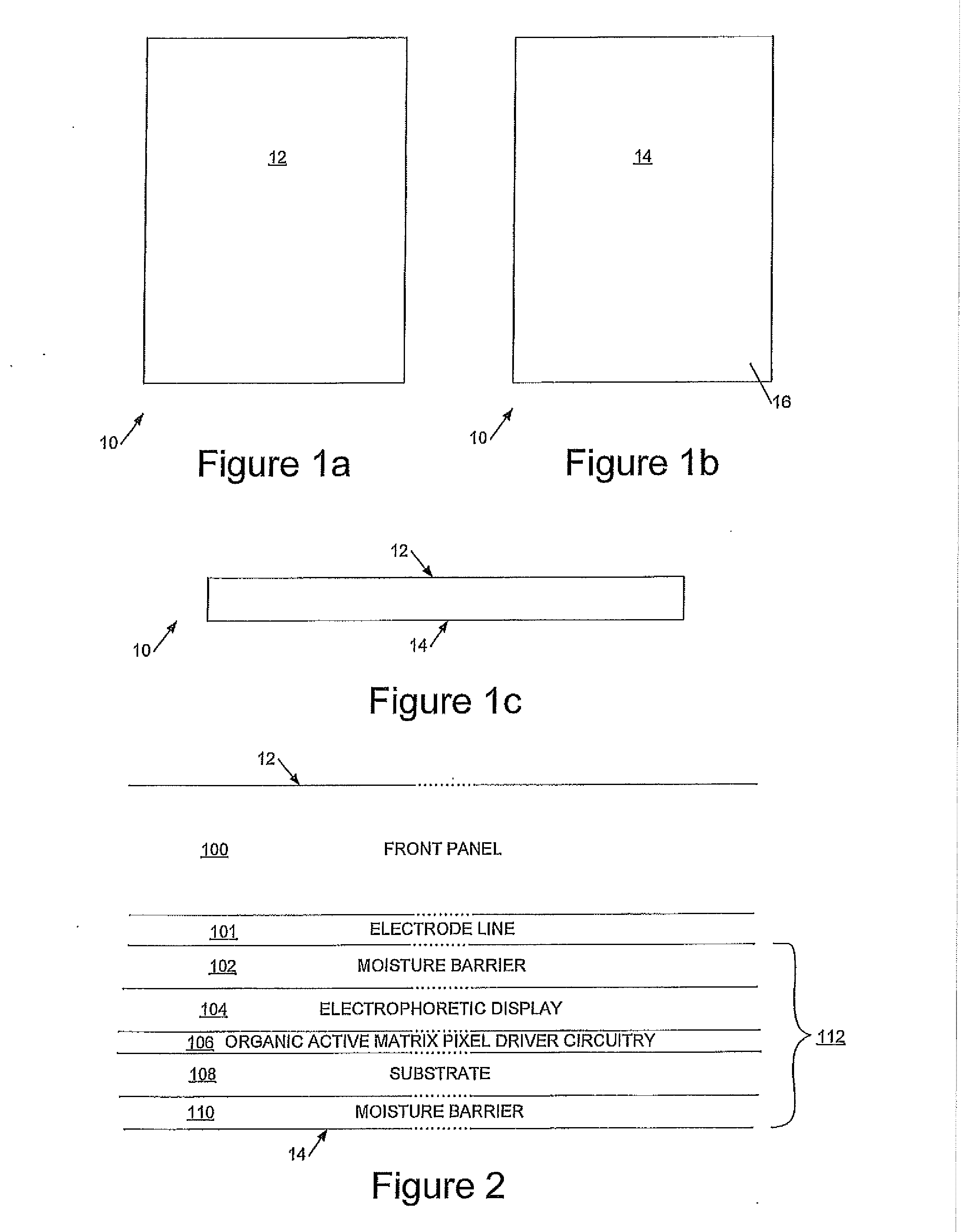
[0029]Referring to FIGS. 1a to 1c, these schematically illustrate an electronic document reading device 10 having a front display face 12 and a rear face 14. As can be seen from FIG. 1c, in preferred embodiments the dis...


PUM


Abstract

We describe a projected capacitance touch screen sensing system comprising: a plurality of touch sensing circuit modules each configured to interpolate between sensed touching of a plurality of adjacent electrodes simultaneously and to output corresponding interpolated touch sense data at a resolution greater than that of a spacing between said electrodes; wherein each of said row and column electrodes has a break to divide the electrode into portions, one of said portions having an electrical connection at one side of the display screen, the other of said portions having an electrical connection at an opposite side of the screen; the sensing system comprising a controller coupled to touch sense data outputs of first to fourth touch sensing circuit modules, said controller configured to select interpolated touch sense data from one of first and second modules to provide row interpolated touch sense data, wherein selection of said first and second modules is responsive to interpolated touch sense data from said third and fourth modules, and wherein said controller is configured to select interpolated touch sense data from one of said third and fourth modules to provide column interpolated touch sense data, wherein selection of said interpolated touch sense data from one of said third and fourth modules is responsive to said interpolated touch sense data from said first and second modules.

Description

CROSS REFERENCE TO RELATED APPLICATION[0001]The present application claims priority to (is a US National Stage Filing of) PCT Application No. PCT / GB2010 / 051601 filed Sep. 24, 2010. The aforementioned PCT application claims priority to British Patent Application No. GB0916806.3 filed Sep. 24, 2009. The entirety of each of the three aforementioned references is incorporated herein by reference for all purposes.BACKGROUND OF THE INVENTION[0002]The present inventions relate to improved techniques for implementing touch screen displays, in particular projected capacitance touch screen sensing for large electrophoretic display screens, and to electronic document readers implementing these techniques.[0003]Background prior art relating to electronic document reading devices can be found in U.S. Pat. No. 6,124,851, US2004 / 0201633, US2006 / 0133664, US2006 / 0125802, US2006 / 0139308, US2006 / 0077190, US2005 / 0260551, U.S. Pat. No. 6,124,851, U.S. Pat. No. 6,021,306, US2005 / 0151742, and US2006 / 01196...

Claims


Application Information

Patent Timeline
Patent Type & Authority Applications(United States)
IPC IPC(8): G06F3/044
CPCG06F3/04883G06F3/0416G06F1/3287G06F3/041Y02B60/1278Y02B60/1282G06F1/3218G06F3/044Y02D10/00G06F3/04166G06F3/0446
Inventor FARMER, STEVEN PAULBARCLAY, DUNCANADCOCK, STEVEWALSH, SEAN
Owner FLEXENABLE LTD
Why Eureka
Try Eureka