Peelable Atraumatic Tip and Body For a Catheter or Sheath

a technology of atraumatic tip and a body, which is applied in the direction of catheters, intravenous devices, guide needles, etc., can solve the problems of separating material, difficult and expensive manufacturing process, and difficulty in providing peeling grooves, and achieve the effect of improving melt adhesion

Active Publication Date: 2008-08-28
ST JUDE MEDICAL ATRIAL FIBRILLATION DIV
View PDF10 Cites 29 Cited by
  • Summary
  • Abstract
  • Description
  • Claims
  • Application Information

AI Technical Summary

Benefits of technology

[0012]In yet another embodiment, a polymeric material of the first strip is not chemically compatible with a polymeric material of the second strip. Consequently, a polymer compatibilizer is introduced into at least one of the polymer materials to improve melt adhesion between the first and second strips of polymer material.

Problems solved by technology

Providing such peeling grooves is a difficult and expensive manufacturing process.
As a result, such prior art tubular bodies end up being quite expensive because of the high cost of the precious heavy metals and the labor intensive manufacturing processes used to manufacture such tubular bodies.
As such, the distal band may not adhere to the material matrix of the tubular body, causing potential material separation and a discontinuity in mechanical strength.
This adds further difficulty and expense to an already difficult and expensive manufacturing process.

Method used


Image

  • Peelable Atraumatic Tip and Body For a Catheter or Sheath
  • Peelable Atraumatic Tip and Body For a Catheter or Sheath
  • Peelable Atraumatic Tip and Body For a Catheter or Sheath

Examples


first embodiment

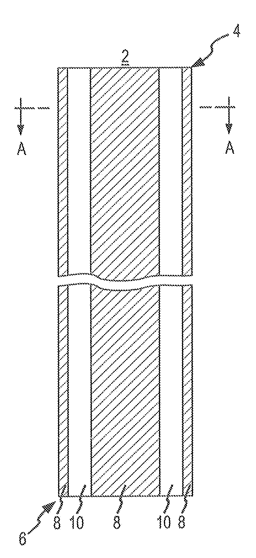
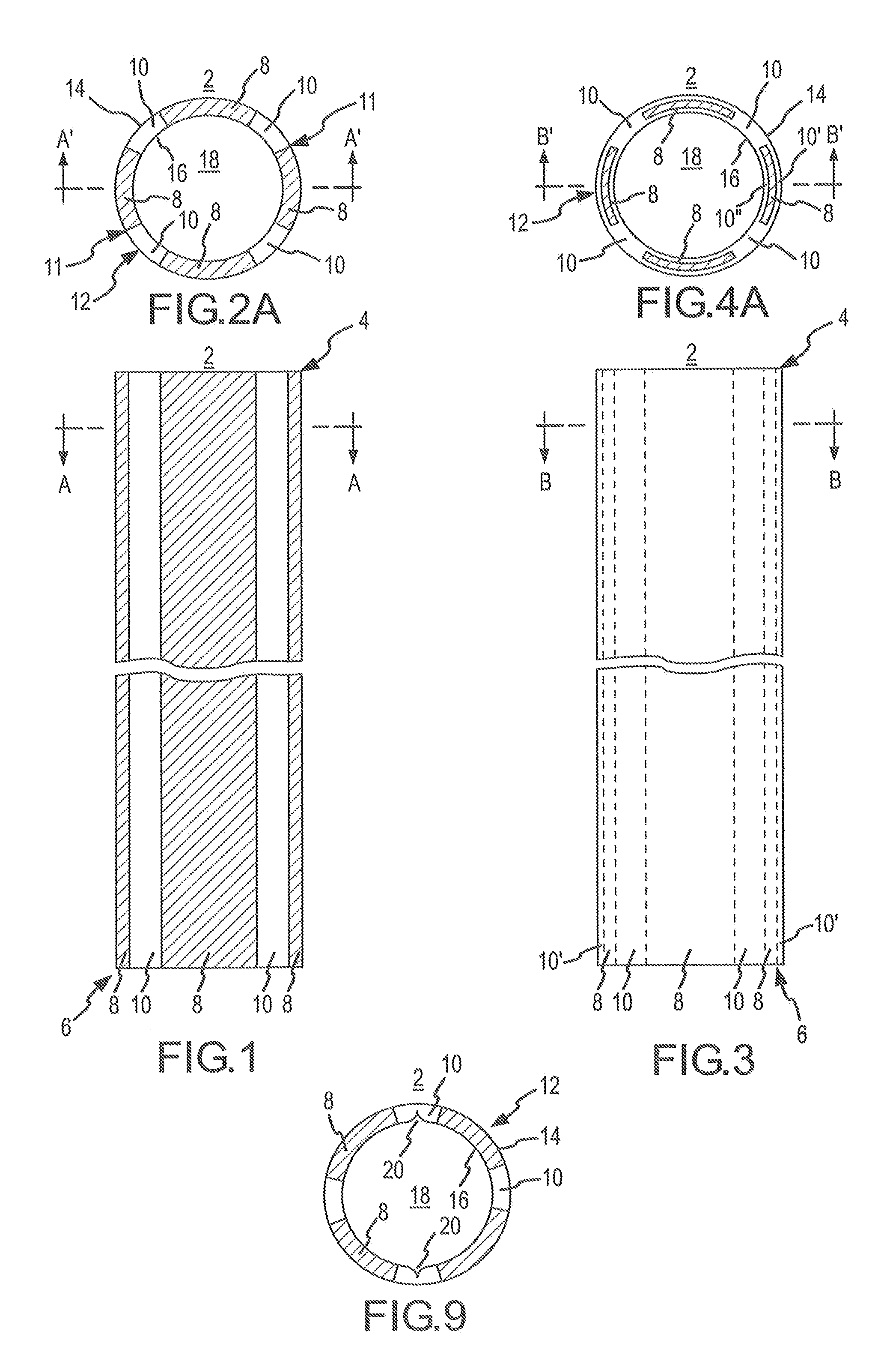
[0048]FIG. 1 is a side elevational view of the present invention including a splittable (i.e., peel-away type) tubular body 2 for a catheter or sheath. The tubular body 2 includes a distal end 4 and a proximal end 6. In the embodiment shown in FIG. 1, the tubular body 2 is formed of at least two integral longitudinal strips 8, 10 of different materials, (e.g., a first polymer and a second polymer). As indicated in FIG. 1, each strip 8, 10 may extend the full length of the tubular body 2 in a generally straight manner.

[0049]The strips 8, 10 will be referred to herein as the first strip 8 and the second strip 10. The material of the first strip 8 will be sufficiently different from the material of the second strip 10 so as to form a stress concentration along the interfacial zones (i.e., borders) 11 between the two strips 8, 10. The stress concentration forms a peel line 11 that acts like a built-in peel groove. As a result, the tubular body 2 may be readily splittable although it la...

second embodiment

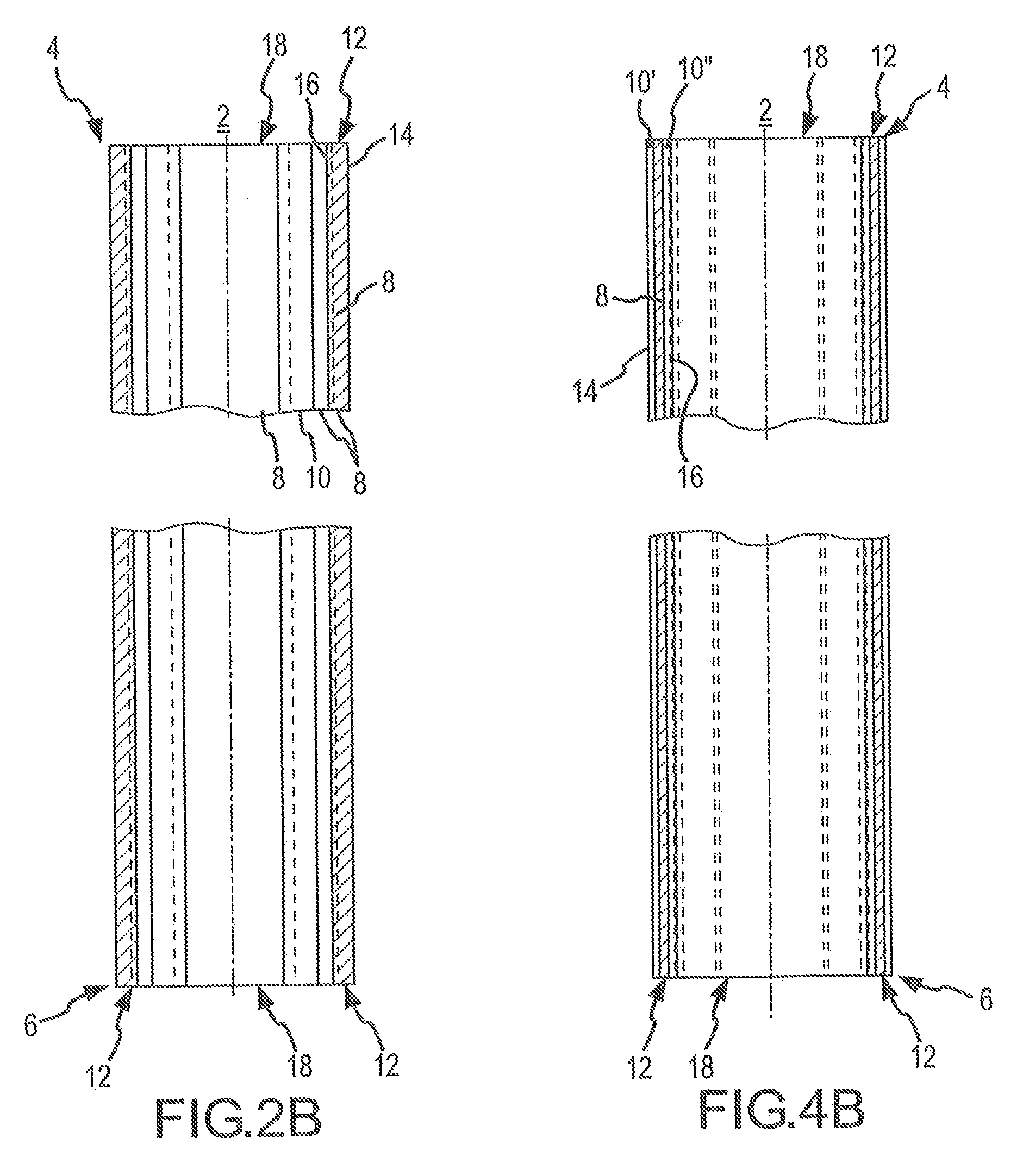
[0070]Similarly, in a second variation of the tubular body 2, as depicted in FIGS. 4E and 4F, which are, respectively, a latitudinal cross-sectional view of the tubular body 2 taken through section line B-B in FIG. 3 and a longitudinal cross-sectional view of the tubular body 2 taken through section line B″′-B″′ in FIG. 4E, the first strips 8 are subjacent to a single layer of second strip material 10, which is an inner layer 10″. Thus, as depicted in FIGS. 4E and 4F, the second strip inner layer 10″ forms the inner circumferential surfaces 16 of the tubular body wall 12 and the first strips 8 form segments of the outer circumferential surface 14 of the tubular body wall 12.

[0071]For a discussion of a third embodiment of the invention, reference is now made to FIGS. 5, 6A and 6B. FIG. 5 is a side elevation view of a third embodiment of the tubular body 2 having a distal end 4 and a proximal end 6 and being formed of at least two integral longitudinal helical strips 8, 10. These stri...

fourth embodiment

[0076]Similarly, in a second variation of the tubular body 2, as depicted in FIGS. 8E and 8F, which are, respectively, a latitudinal cross-sectional view of the tubular body 2 taken through section line D-D in FIG. 7 and a longitudinal cross-sectional view of the tubular body 2 taken through section line D″′-D″′ in FIG. 8E, the first strips 8 are subjacent to a single layer of second strip material 10, which is an outer layer 10′. Thus, as depicted in FIGS. 8E and 8F, the second strip outer layer 10′ forms the outer circumferential surface 14 of the tubular body wall 12 and the first strips 8 form segments of the inner circumferential surface 16 of the tubular body wall 12.

[0077]The first strips 8 and the second strips 10 can be formed from two compatible polymers or polymeric compounds into an integral tubular body 2 via co-extrusion, co-injection molding, or co-compression molding processes. Candidate polymeric materials include thermoplastic and thermosetting polymer systems.

[007...


PUM

PropertyMeasurementUnit
stress concentrationaaaaaaaaaa
stress concentrationsaaaaaaaaaa

Abstract

A splittable/peelable tubular body (2) of a catheter or sheath wherein the tubular body (2) has a splittable/peelable atraumatic tip (14) is disclosed. The atraumatic tip (4) is generally softer than the tubular body (2). The tubular body (2) and atraumatic tip (4) each comprise a peel mechanism longitudinally extending along their respective lengths. The peel mechanisms are formed by longitudinally extending regions of interfacial bonding (11) between first and second longitudinally extending strips (8, 10) of polymer material. Each strip (8, 10) forms at least a portion of an outer circumferential surface of the tubular body (2) and atraumatic tip (4). A region of stress concentration extends along the region of interfacial bonding. The stress concentration facilitates the splitting of the tubular body (2) and atraumatic tip (4) along their respective peel mechanisms.

Description

CROSS-REFERENCE TO RELATED APPLICATIONS[0001]The present application claims priority to U.S. provisional patent application No. 60 / 675,973 (“the '973 application”), which was filed on 28 Apr. 2005; and the present application also claims priority to U.S. provisional patent application No. 60 / 677,423 (“the '423 application”), which was filed on 3 May 2005. This application is also related to international patent application no. PCT / US2006 / xxxxxx (docket no. 0B-046802WO), entitled “Tubular Body for a Catheter or Sheath” being filed concurrently herewith (the 'xxx application). The '973, '423, and 'xxx applications are hereby incorporated by reference as though fully set forth herein.BACKGROUND OF THE INVENTION[0002]The present invention relates to bodies for catheters and sheaths, and to tips for use in conjunction with such catheters and sheaths, as wells as to methods of manufacturing and using the same. More particularly, the present invention relates to splittable and radiopaque b...

Claims


Application Information

Patent Timeline
Patent Type & Authority Applications(United States)
IPC IPC(8): A61M25/00
CPCA61M25/0668A61M2025/0687Y10T29/49826A61M25/001
Inventor GUO, XIAOPINGSTEHR, RICHARD E.EPSHTEYN, VITALIY G.HOLMAN, BRUCE P.SAUTER, DONALD A.THORSTENSON, CHAD A.POTTER, DANIEL J.PERERA, NALIN S.
Owner ST JUDE MEDICAL ATRIAL FIBRILLATION DIV
Why Eureka
Try Eureka