High resolution gas gauge proximity sensor

a gas gauge and proximity sensor technology, applied in the field of gas gauges, can solve the problems of significant affecting the measurement, ineffective process, unpredictable measurement error,

Active Publication Date: 2005-11-03
ASML HLDG NV
View PDF28 Cites 23 Cited by
  • Summary
  • Abstract
  • Description
  • Claims
  • Application Information

AI Technical Summary

Benefits of technology

[0008] The present invention reduces the problem of changes in the local environment by causing the measurement nozzle and the reference nozzle to react as if they

Problems solved by technology

However, this process becomes ineffective when high-resolution measurements, such as those on the order of nanometers, are required.
When a small measurement is needed, local environmental differences between the measurement nozzle and the reference nozzle significantly affect the measurements, even when the nozzles are only a centim

Method used


Image

  • High resolution gas gauge proximity sensor
  • High resolution gas gauge proximity sensor
  • High resolution gas gauge proximity sensor

Examples


Embodiment Construction

[0027] While specific configurations and arrangements are discussed, it should be understood that this is done for illustrative purposes only. A person skilled in the pertinent art will recognize that other configurations and arrangements can be used without departing from the spirit and scope of the present invention. It will be apparent to a person skilled in the pertinent art that this invention can also be employed in a variety of other applications.

Introduction

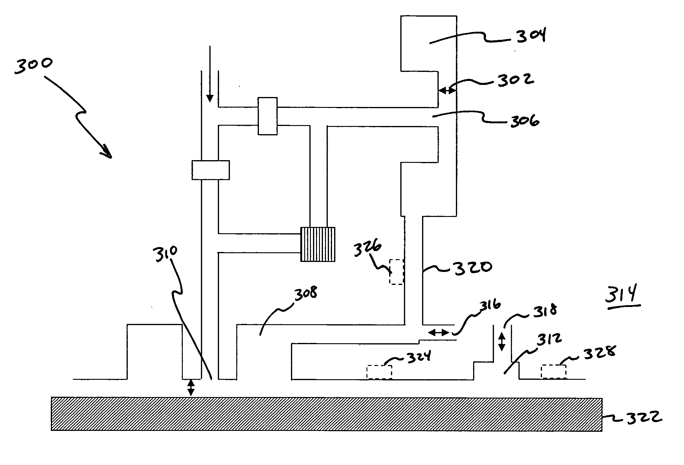
[0028] In order to understand the benefits of the present invention, it is helpful to describe a generic system, such as that found in U.S. Pat. No. 4,953,388 issued to Barada and U.S. Pat. No. 4,550,592 issued to Dechape, each of which is incorporated herein by reference in its entirety. FIG. 7 is a block diagram of a conventional air gauge 700. An air pump 702 supplies air to a mass flow controller 704. Mass flow controller 704 maintains a constant rate of air flow into air gauge 700. The air then passes through filt...


PUM


Abstract

In a gas gauge, effects due to changes in the local environment are reduced by causing a measurement nozzle and a reference nozzle to react as if they were co-located, or located at approximately the same position. This is achieved by venting the reference nozzle in very close proximity to the measurement nozzle. A reference chamber surrounding the reference plate and reference nozzle is vented at approximately the same location as the measurement nozzle. In an embodiment for use in a vacuum environment, the measurement nozzle is surrounded with an annular ring. The measurement annular ring is connected to an annular ring around the reference nozzle, which acts to co-locate the reference nozzle and the measurement nozzle. To avoid choked flow, another annular ring or rings may be placed around the measurement annular ring.

Description

BACKGROUND OF THE INVENTION [0001] 1. Field of the Invention [0002] This invention relates to the field of gas gauges for use in vacuum or ambient environments. [0003] 2. Related Art [0004] A typical air gauge is very sensitive to environmental effects, such as the pressure, humidity, and temperature of the air. One method of canceling out these effects is to use a reference nozzle and a measurement nozzle. The measurement nozzle uses air flow pressure differences to measure a distance between the nozzle and a surface. For example, the surface may be a semiconductor wafer or LCD panel. The reference nozzle discharges air toward a reference plate. The surface of the reference plate is located at a pre-determined distance from the reference nozzle. The distance of the measurement nozzle to the surface can be determined by comparing the difference between the reference air flow pressure and the measurement airflow pressure. [0005] If the properties of environmental effects are uniform ...

Claims


Application Information

Patent Timeline
IPC IPC(8): G01L7/00G01B13/12G01L19/02G01L19/04
CPCG01L19/0092G01B13/02G03F9/00G03F9/7057
Inventor CARTER, FREDERICK MICHAELKOCHERSPERGER, PETER
Owner ASML HLDG NV
Why Eureka
Try Eureka