Diagnostic apparatus for evaporative emission control system

a technology of evaporative emission control and diagnostic equipment, which is applied in the direction of machines/engines, fluid-tightness measurement, instruments, etc., can solve the problems of difficult to determine the accurate leakage of evaporated fuel, difficult to perform accurate leakage diagnosis,

Inactive Publication Date: 2005-11-03
SUBARU CORP
View PDF4 Cites 7 Cited by
  • Summary
  • Abstract
  • Description
  • Claims
  • Application Information

AI Technical Summary

Benefits of technology

[0009] In view of such circumstances, it is an object of the present invention to provide a diagnostic apparatus f

Problems solved by technology

However, when a part of the system is broken or disrupted for some reasons, the evaporated fuel is discharged to the atmosphere.
However, in the technology disclosed in the aforementioned JP-A-2001-41116, since the pressure change amounts P1, P2 are measured by sealing the evaporati

Method used


Image

  • Diagnostic apparatus for evaporative emission control system
  • Diagnostic apparatus for evaporative emission control system
  • Diagnostic apparatus for evaporative emission control system

Examples


Embodiment Construction

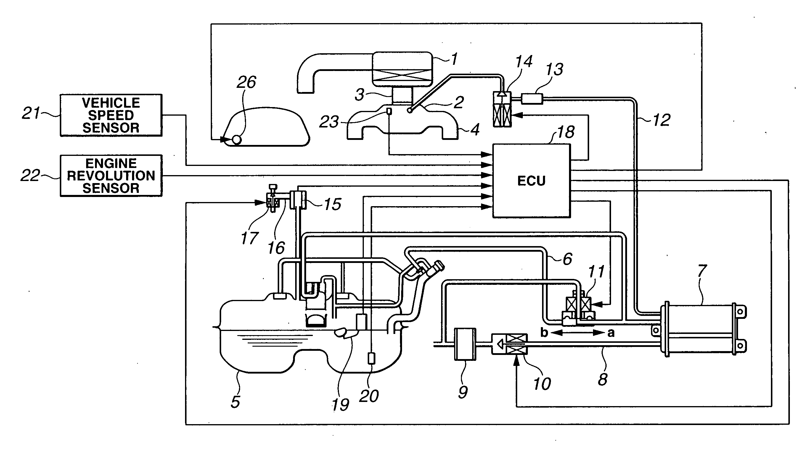
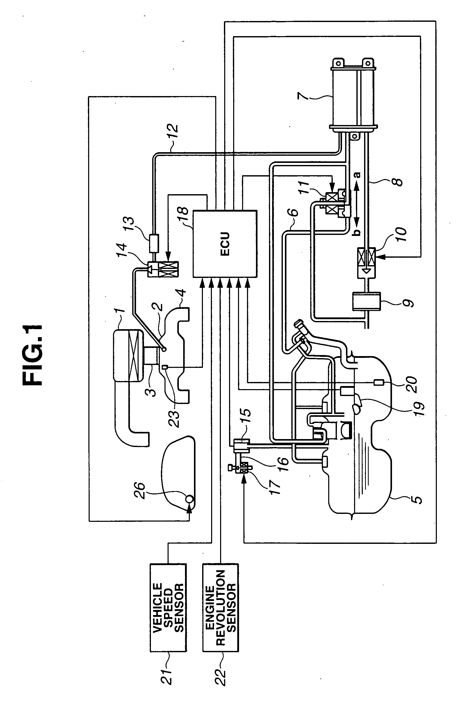
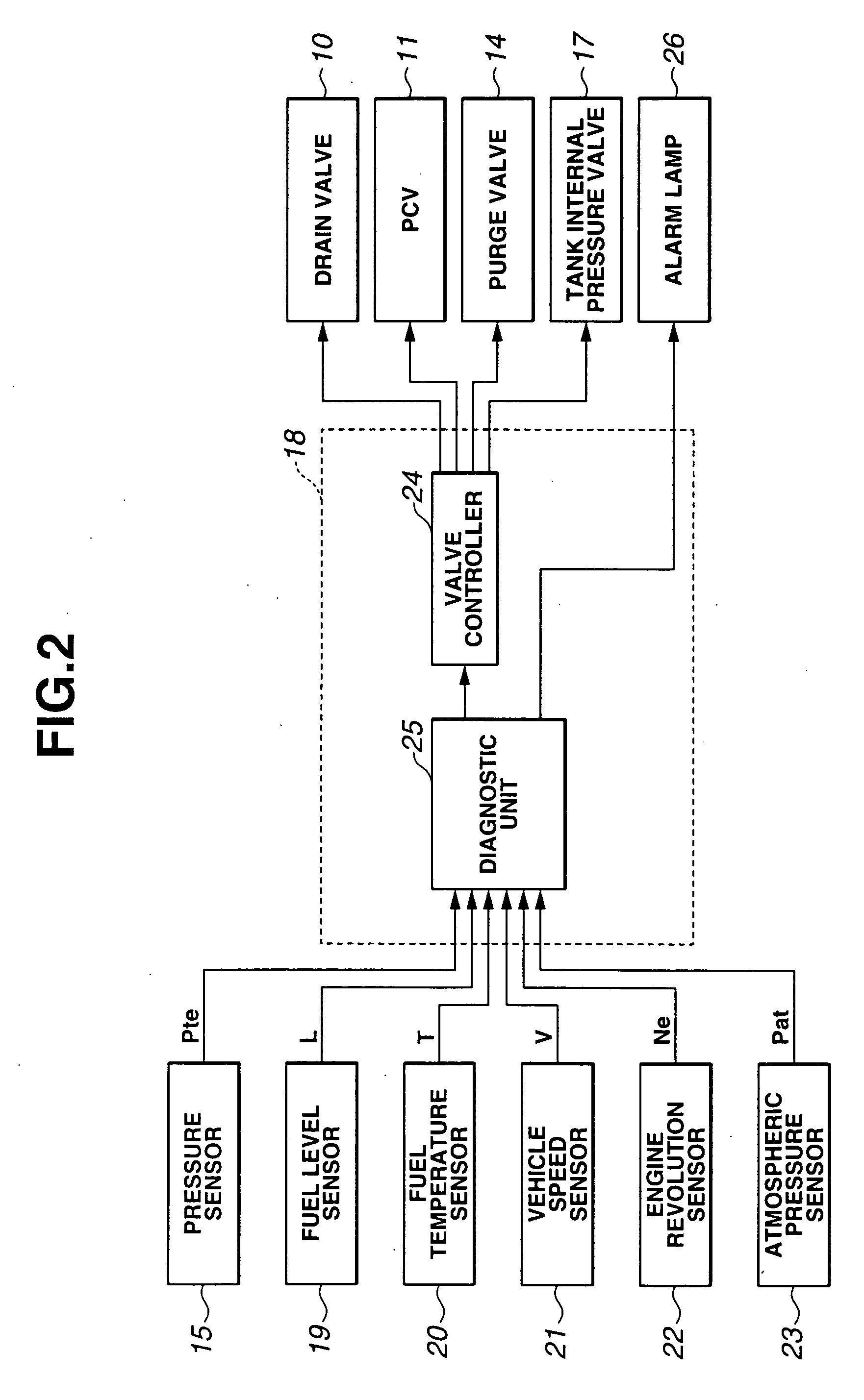
[0021] Embodiments of the present invention will be described by referring now to drawings. The drawings are relating to the first embodiment of the invention, in which FIG. 1 is a schematic block diagram of an evaporative emission control system; FIG. 2 is a functional block diagram of an ECU; FIG. 3 is a flowchart of a main routine of the leak diagnosis; FIG. 4 is the flowchart of Mode A running subroutine in FIG. 3; FIG. 5 is the flowchart of Mode B running subroutine in FIG. 3; FIG. 6 is the flowchart of Mode C running subroutine in FIG. 3; FIG. 7 is the flowchart of Mode D running subroutine in FIG. 3; FIG. 8 is the flowchart of Mode E running subroutine; FIG. 9 is a timing chart of leak diagnosis.

[0022] In FIG. 1, air from which dust or the like in the atmosphere is removed by an air cleaner 1 is controlled in its flow rate according to an opening degree of an electric throttle valve, not shown. The throttle valve is provided in a throttle body 3 mounted in an intake passage ...


PUM


Abstract

The present invention provides a diagnostic apparatus for an evaporative emission control system which can accurately execute leak diagnosis under a stable condition. An ECU clocks a time td2 until the internal pressure value Pte of the evaporative emission control system sealed at the negative pressure reaches the target internal pressure value Pd, sets the pressure change measuring time te2 based on the clocking time td2, and measures the pressure change amount P1 which varies after the internal pressure value Pte of the evaporative emission control system reaches the target internal pressure value Pd for a pressure change measuring time te2. Then, the ECU sets the determination value Pth0 based at least on the spatial capacity of the evaporative emission control system, and determines whether the evaporative emission control system is normal or abnormal based on the pressure change amount P1.

Description

[0001] This application claims benefit of Japanese Application No. 2004-93477 filed on Mar. 26, 2004, the contents of which are incorporated by this reference. BACKGROUND OF THE INVENTION [0002] 1. Field of the Invention [0003] The present invention relates to a diagnostic apparatus for an evaporative emission control system and, more specifically, to a leak diagnosis of an evaporative emission control system including a fuel tank. [0004] 2. Description of the Related Art [0005] Known is an internal combustion engine including an evaporative emission control system for preventing evaporated fuel in a fuel tank to be discharged in the atmosphere. In this system, evaporated fuel (evaporation gas) generated in the fuel tank is temporarily adsorbed by an adsorbent filled in a canister, and the adsorbed evaporated fuel is discharged to an intake system in an internal combustion engine via a purge passage (or line) under predetermined operating conditions. However, when a part of the syst...

Claims


Application Information

Patent Timeline
IPC IPC(8): G01M3/32F02M25/08G01M99/00
CPCG01M3/3236
Inventor TAKAHASHI, DAISUKEAIHARA, MASAAKINAKOJI, YASUSHI
Owner SUBARU CORP
Why Eureka
Try Eureka