Microwave transponder

a transponder and microwave technology, applied in the direction of mechanical actuation of burglar alarms, instruments, transmission monitoring, etc., can solve the problems of limiting the operating range of identification, affecting the operation efficiency of the antenna on the flexible substrate, and large-sized and inoperable antennas, so as to improve the operating range and reduce the power of microwaves

Active Publication Date: 2005-11-03
SAMSUNG ELECTRONICS CO LTD
View PDF13 Cites 7 Cited by
  • Summary
  • Abstract
  • Description
  • Claims
  • Application Information

AI Technical Summary

Problems solved by technology

The active type, which includes an energy source, provides a long communication distance, but is large-sized and inoperative in conditions when it is hard to obtain the power source.
When the transponder is bendable, the antenna on a flexible substrate is adversely affected by various distortions such as bending.
Accordingly, the impedances of the antenna and the semiconductor chip mismatch, thus limiting an operating range of the identification.
Specifically, if the transponder is constructed to adhere on a curved installation, its operating range is limited so as to depreciate the performance or results in standstill.
However, the increase of the microwave power is restricted due to safety regulation or other legislation.

Method used


Image

  • Microwave transponder
  • Microwave transponder
  • Microwave transponder

Examples


Embodiment Construction

[0029] Reference will now be made in detail to exemplary embodiments of the present invention, examples of which are illustrated in the accompanying drawing figures, wherein like reference numerals refer to the like elements throughout. Exemplary embodiments are described below in order to explain the present invention by referring to the drawing figures.

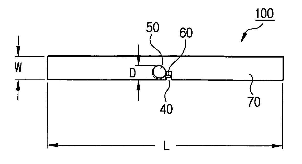
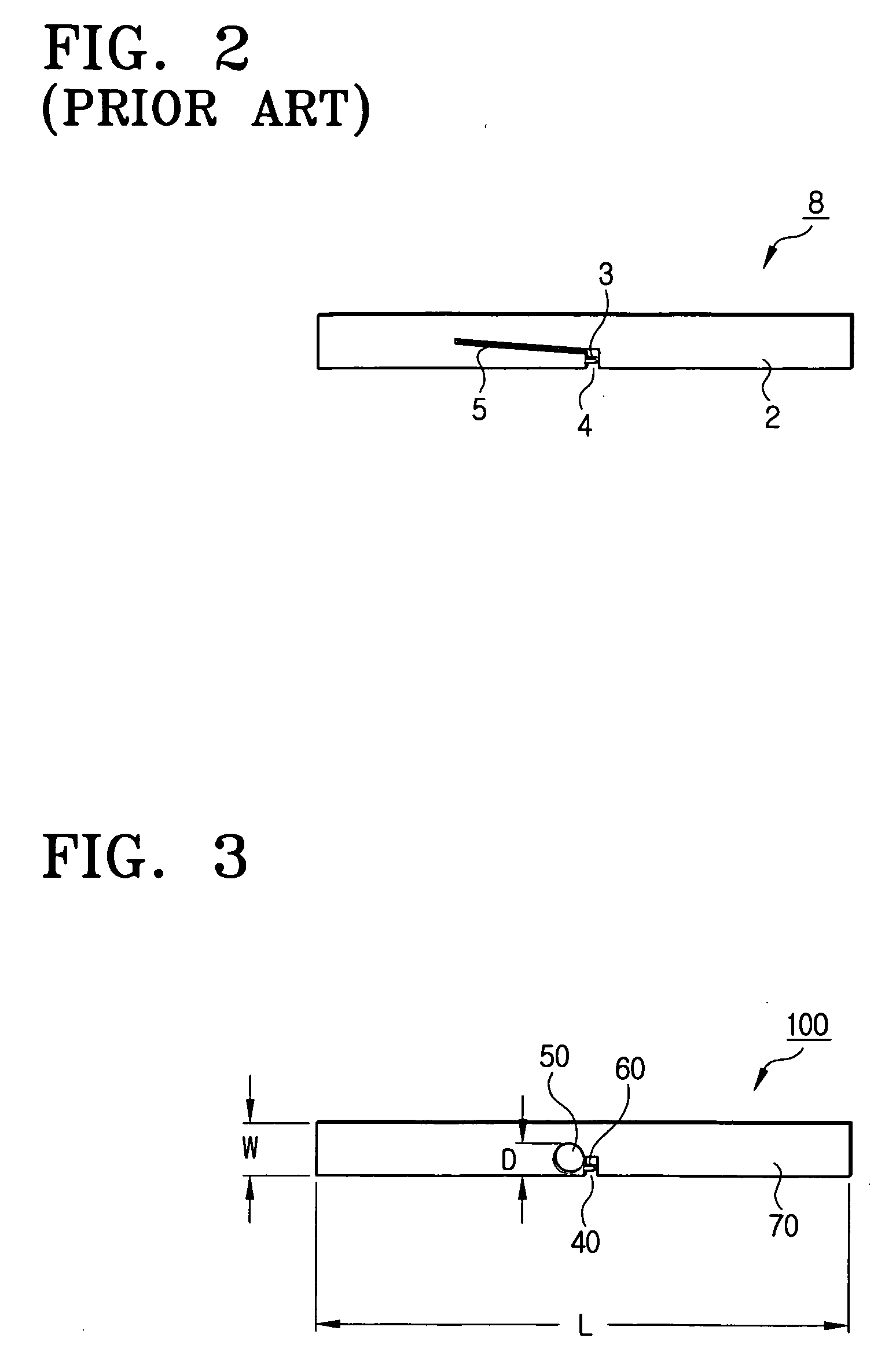
[0030]FIG. 3 is a plan view of a microwave transponder 100 according to an exemplary embodiment of the present invention. Referring to FIG. 3, the microwave transponder 100 includes a conductive plate 70, a semiconductor chip 60, and a window 50. The conductive plate 70 is thin and flexible, and includes a body of an antenna which is not shown. The semiconductor chip 60 is mounted near or within a terminal gap 40 as in the conventional arrangement, and includes a rectifier which is not shown. The terminal gap 40 is located in the vicinity of the center of the conductive plate 70. The window 50 extends from the terminal gap 40 and p...


PUM


Abstract

A microwave transponder. The microwave transponder includes a conductive plate including an antenna, and a semiconductor chip disposed within a terminal gap located in a vicinity of a center of the conductive plate. A window of a predetermined shape is formed to extend from the terminal gap toward a side of the conductive plate. The perfect impedance matching is fulfilled even when the transponder is bent. Since the return loss of the electromagnetic power is reduced at least in a quarter through the impedance matching, the energy transferred to the transponder is maximized.

Description

CROSS-REFERENCE TO RELATED APPLICATIONS [0001] This application claims the benefit of Korean Patent Application No. 2004-27977, filed on Apr. 22, 2004 in the Korean Intellectual Property Office, the disclosure of which is incorporated herein by reference in its entirety. BACKGROUND OF THE INVENTION [0002] 1. Field of The Invention [0003] The present invention is related generally to a microwave transponder. More specifically, the present invention pertains to a microwave transponder having a circular window structure that fulfills impedance matching in order to transfer maximum energy. [0004] 2. Description of The Related Art [0005] A microwave transponder is utilized in various applications. For example, a radio frequency identification (RFID) system, which is one of the various applications, is coming into increasing use in industry. [0006]FIG. 1 is a schematic block diagram of a conventional RFID system. Referring to FIG. 1, the RFID system includes a transponder 10, a reader 20,...

Claims


Application Information

Patent Timeline
Patent Type & Authority Applications(United States)
IPC IPC(8): G06K19/07G06K19/077H01Q1/22H01Q1/36H01Q9/16H04B1/59
CPCG06K19/07749H01Q1/2208G06K19/07786D21H17/68D21H27/20
Inventor TIKOV, YURIWON, JONG-HWAKU, JA-NAM
Owner SAMSUNG ELECTRONICS CO LTD
Why Eureka
Try Eureka