Magnetostrictive actuator in a magnetic head

a magnetic head and actuator technology, applied in the field of magnetic disk storage systems, can solve the problems of reducing the flying height, undesirable, increasing the temperature of the sensor, etc., and reducing the reliability of the sensor

Inactive Publication Date: 2005-11-03
HEADWAY TECH INC
View PDF9 Cites 20 Cited by
  • Summary
  • Abstract
  • Description
  • Claims
  • Application Information

AI Technical Summary

Problems solved by technology

Reducing the flying height is, however, undesirable because of the increased likelihood of head disk interference or even a head crash.
Thermal protrusion does not reduce the slider flying height, but it increases the sensor temperature and thus reduces reliability of the sensor.
In addition, thermal expansion is relatively slow in response time.
Electrostatic attractive force generation between head and media through a voltage application at the slider body has deficiency in potential “pull-in” crash due to the non-linearity in actuation outside the narrow nominal range.
Also, the electrical charge could discharge to result in pin hole formation at the surface of the recording disk, creating a potential reliability problem of corrosion.

Method used


Image

  • Magnetostrictive actuator in a magnetic head
  • Magnetostrictive actuator in a magnetic head
  • Magnetostrictive actuator in a magnetic head

Examples


Embodiment Construction

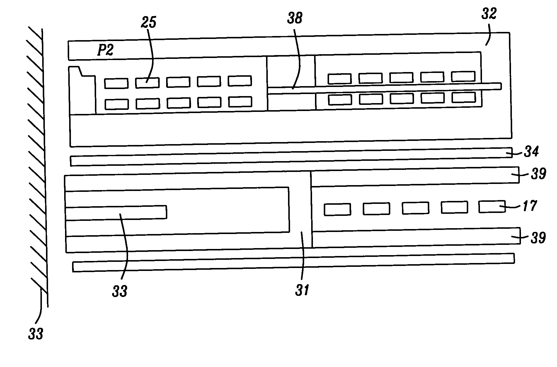
[0015] The present invention discloses a new method of controlling magnetic spacing. It utilizes a magnetostrictive actuator, comprising single or multiple pairs of magnetostrictive elements and their associated conductor coils. A magnetic field is generated by passing electrical current through the conductor coils. The field in turn will saturate the actuator and cause the magnetostrictive elements to contract or expand, thus moving the read / write element in the slider along the desired direction.

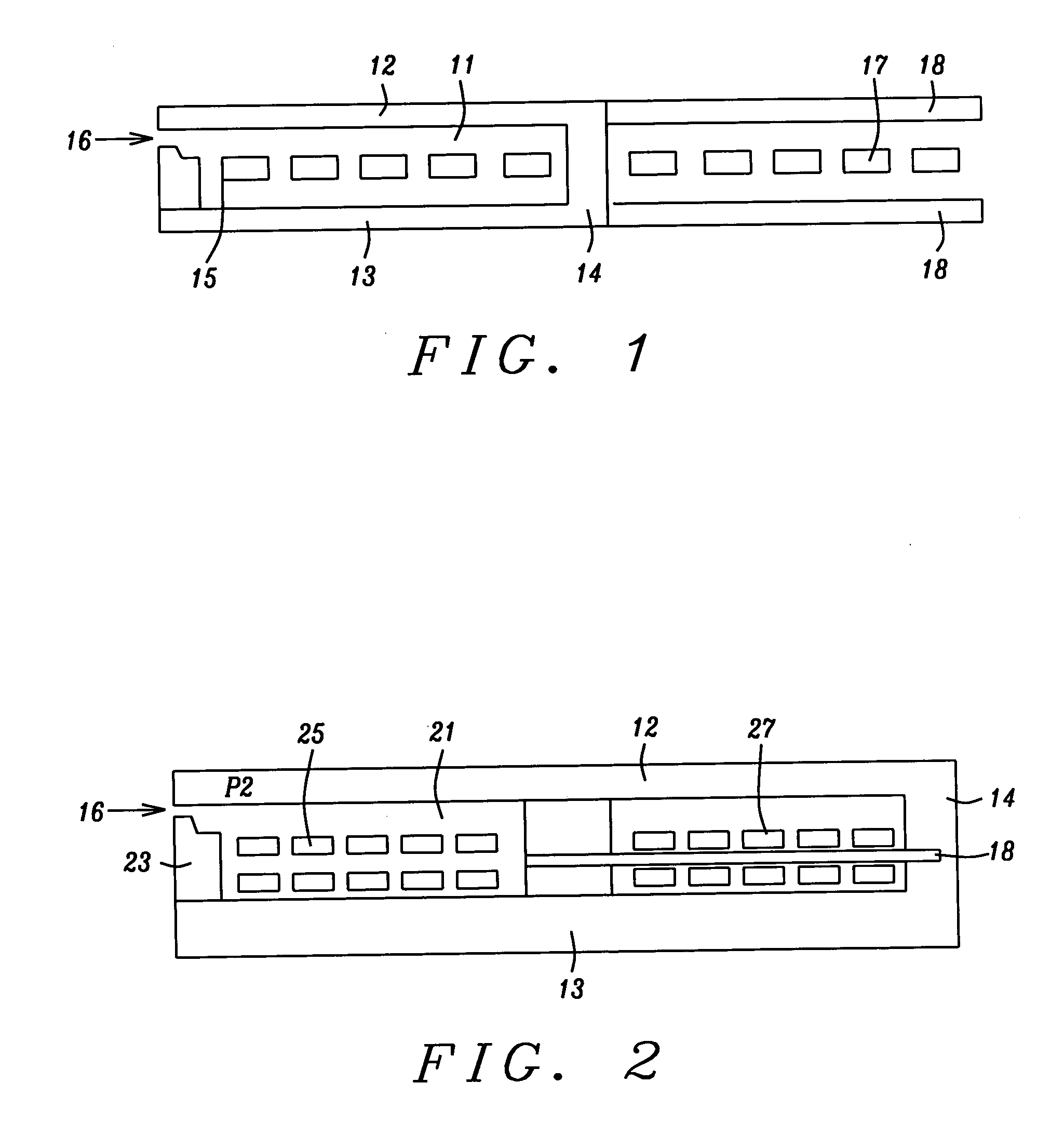
[0016] A preferred embodiment of this invention is to embed the actuator into a slider element during wafer fabrication. The actuator position can be determined by considering the desired read / write element actuation and the complexity of wafer process integration. Another embodiment of the invention requires individual conductor coils for write field generation and for saturation of the actuator. A schematic diagram of this design is shown in FIG. 1. Multiple magnetostrictive actuators c...


PUM

PropertyMeasurementUnit
distanceaaaaaaaaaa
distanceaaaaaaaaaa
currentaaaaaaaaaa

Abstract

In order to obtain improved magnetic track density, it is desirable to bring the read and write elements as close to the recording surface as possible, short of actually touching it. This has been achieved by utilizing a magnetostrictive actuator, comprising single or multiple pairs of magnetostrictive elements and their associated conductor coils. A magnetic field is generated by passing electrical current through the conductor coils. This field will saturate the actuator and cause the magnetostrictive elements to contract or expand, thus moving the read/write element whenever so desired.

Description

FIELD OF THE INVENTION [0001] The invention relates to the general field of magnetic disk storage systems with particular reference to dynamically adjusting a part of the ABS (air bearing surface) in order to vary the distance between the read and / or write elements and the recording media. BACKGROUND OF THE INVENTION [0002] It is well known that increasing areal density in magnetic recording requires a corresponding reduction in the magnetic spacing between the write / read elements and the recording media. Previous inventions in this field have employed piezoelectric elements, thermal heating coils, and electrostatic attraction to reduce magnetic spacing. For example, a piezoelectric transducer (PZT) was applied to the suspension so as to reduce the flying height at the head region. Reducing the flying height is, however, undesirable because of the increased likelihood of head disk interference or even a head crash. [0003] Thermal protrusion does not reduce the slider flying height, ...

Claims


Application Information

Patent Timeline
Patent Type & Authority Applications(United States)
IPC IPC(8): G11B5/55G11B5/56G11B5/60G11B5/58
CPCG11B5/5552G11B5/58G11B5/56
Inventor HU, DAVIDDOVEK, MORISLIU, KOWANG
Owner HEADWAY TECH INC
Why Eureka
Try Eureka