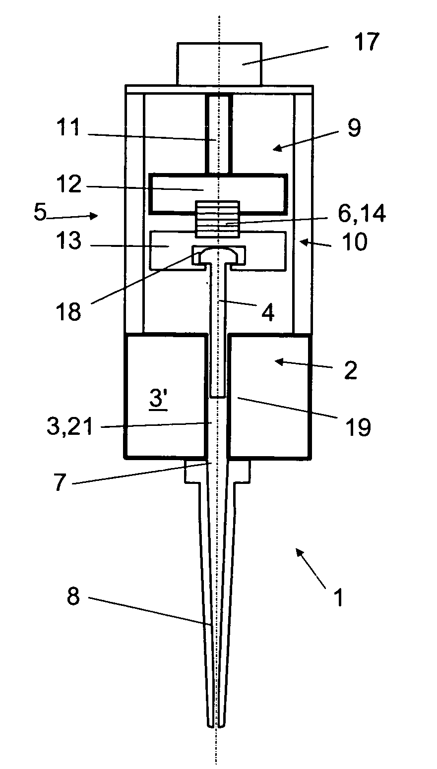
Device for aspirating and dispensing liquid samples
a liquid sample and aspiration device technology, applied in the direction of feed devices, withdrawing sample devices, liquid/fluent solid measurements, etc., can solve the problems of limiting the resolution of the quantity of liquid to be dispensed, droplet size and reproducibility, and two-dimensional combs of pipettes, however, are typically no longer sufficient for the current demands for sample throughpu
- Summary
- Abstract
- Description
- Claims
- Application Information
AI Technical Summary
Benefits of technology
Problems solved by technology
Method used
Image
Examples
first embodiment
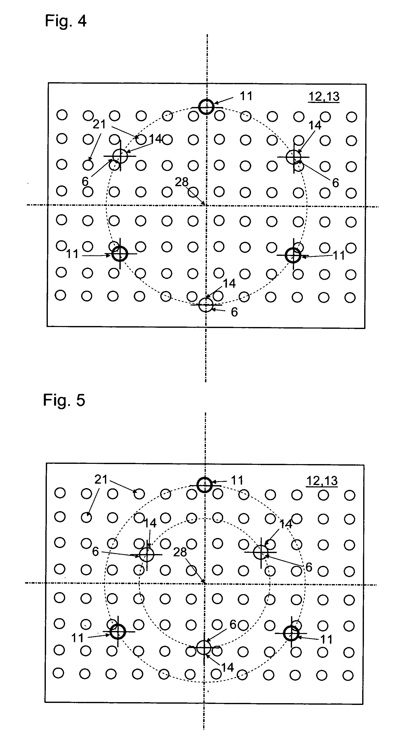
[0037]FIG. 4 shows, in a horizontal projection, a layout of the piston drive 5 according to a Three spindles 11 and three pulse generators 6 are each positioned at the same distance from the center of the cylinder block 3′ and / or the two plates 12, 13, with this same distance also lying between them and the nearest pulse generator 6 and / or spindle 11. A trigonal symmetry whose center 28 lies in the center of the cylinder block 3′ and / or the two plates 12, 13 results from this. This symmetry allows uniform distribution of the forces in the plates 12, 13 and thus uniform displacement of the plates with the first drive 9 and the second drive 10. In this case as well, the liquid is fed into the tip with the first drive, so that before each pulse by the second drive, a coherent liquid column fills up the active space of cylindrical space 3, line 7, and tip 8. The layout described has the advantage that the levels of the plates 12, 13 are never redundant and that only three piezoelectric...
second embodiment
[0038]FIG. 5 shows a horizontal projection of a layout of the piston drive according to a In contrast to FIG. 4, in this case the spindles 11 and the pulse generators 6 are not located on a common graduated circle (indicated with dashed lines). However, the spindles 11 and / or the pulse generators 6 each define a triangle, whose center of gravity always corresponds with the center of symmetry 28, in both FIG. 4 and in FIG. 5. The symmetry achieved in this way allows uniform distribution of the forces in the plates 12, 13 and therefore uniform displacement of these plates with the first drive 9 and the second drive 10. Further arrangements which correspond to this symmetry principle are included in the extent of this invention.
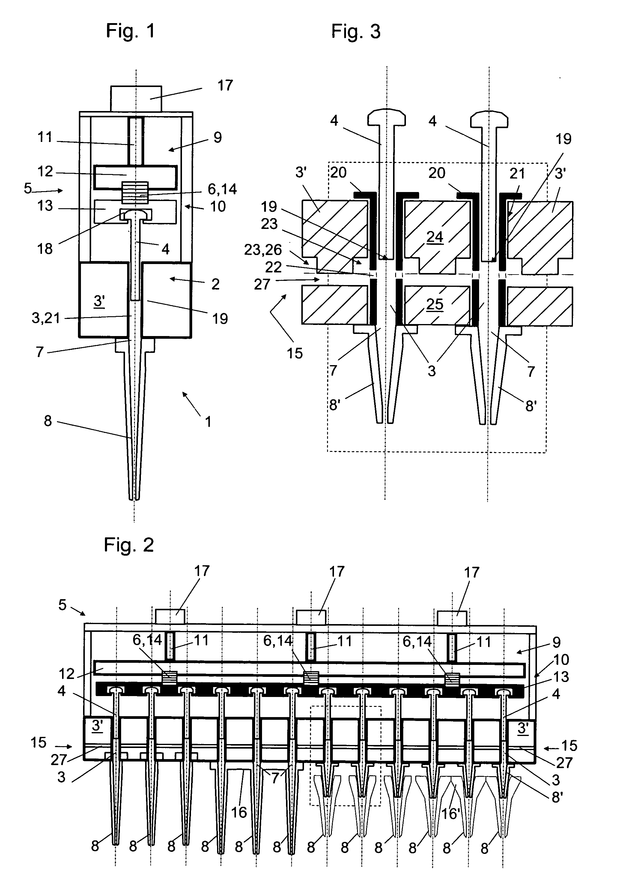
[0039]FIG. 6 shows an enlarged detail from FIG. 2, corresponding to the field indicated there and according to an especially preferred embodiment. This embodiment preferably comprises borings 21 in the cylinder block 3′, which are used as cylinders 3 (cf. FIG. ...
PUM
| Property | Measurement | Unit |
|---|---|---|
| volume | aaaaa | aaaaa |
| voltage | aaaaa | aaaaa |
| volumes | aaaaa | aaaaa |
Abstract
Description
Claims
Application Information
 - R&D
- Intellectual Property
- Life Sciences
- Materials
- Tech Scout
- Unparalleled Data Quality
- Higher Quality Content
- 60% Fewer Hallucinations
Browse by: Latest US Patents, China's latest patents, Technical Efficacy Thesaurus, Application Domain, Technology Topic, Popular Technical Reports.
© 2025 PatSnap. All rights reserved.Legal|Privacy policy|Modern Slavery Act Transparency Statement|Sitemap|About US| Contact US: help@patsnap.com


